| DESCRIPTION | HISTORY |
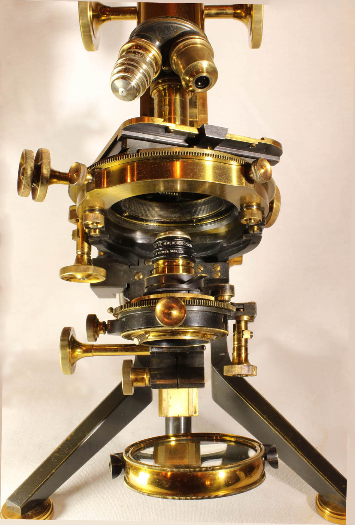
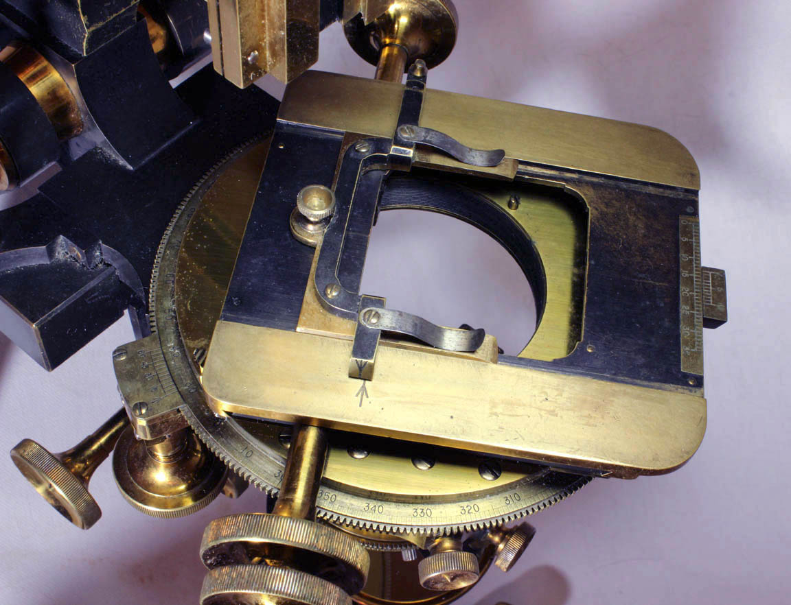
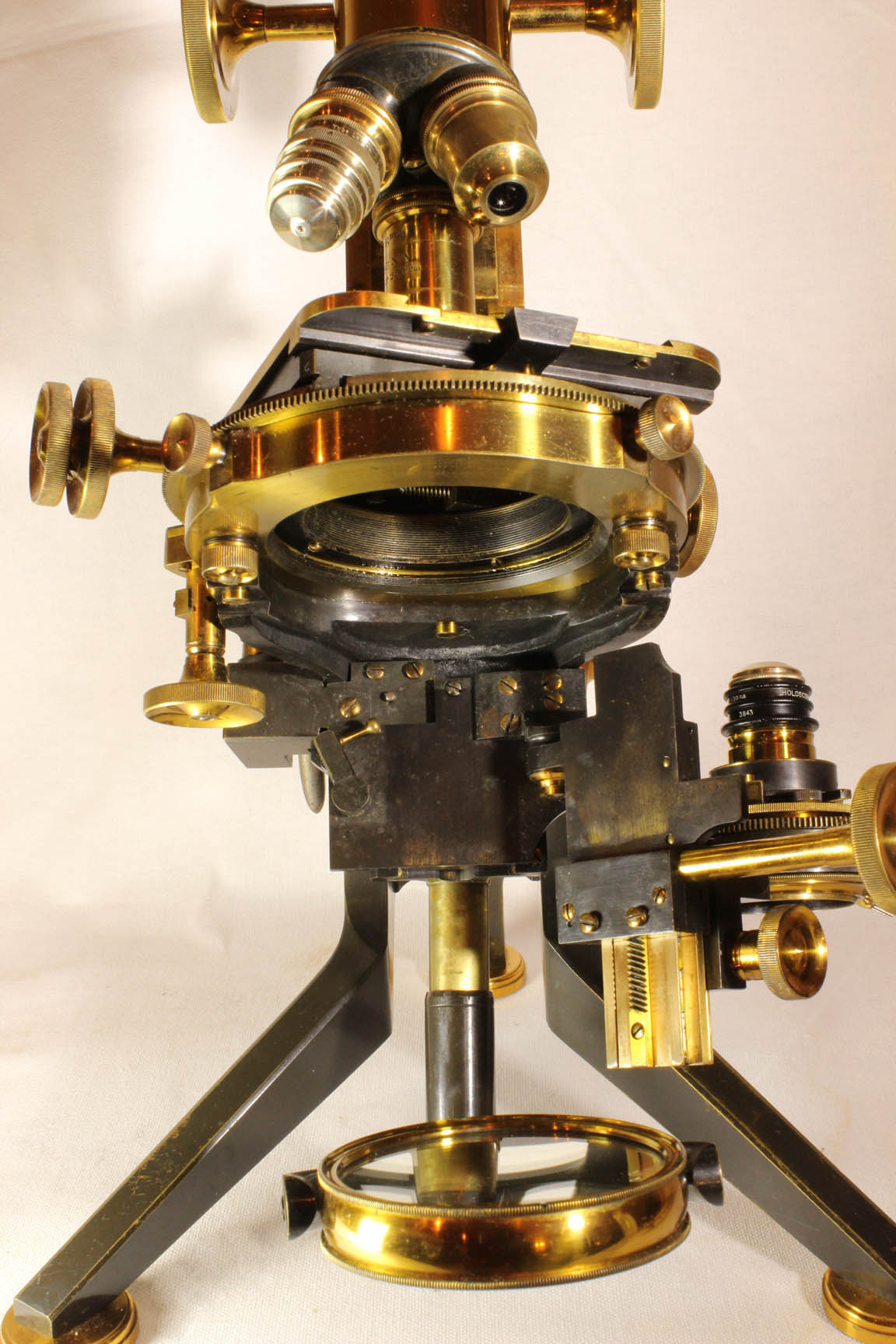
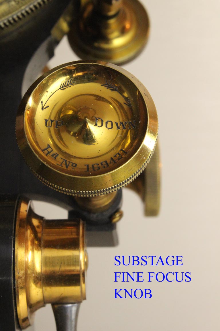 Fine substage focus* is via a knob protruding upward above the stage.
This knob, unlike the main fine focus knob, is not calibrated, but does
have arrows showing the direction the
substage is moved; clockwise moves the substage down, counterclockwise,
up. There is a ring to support a condenser which has controls for
centering the condenser. The condenser housing can swing out of the
optical axis on a hinge, a standard feature for the Grand Van Heurck by
this time. A tiny brass handle acts on the piece locking the condenser
assembly in the normal position. Another
feature on this microscope is the optional mounting of the substage
support ring on a sliding bar* in a dovetail fitting so that the
substage may be set at any desired position, irrespective of the
rackwork, which operates independently; this allows the use of all
substage accessories, some of
which would otherwise be too tall to install without this flexibility.
This fitting has a lacquered brass knurled knob to lock it in any
desired position on the dovetail slide.
Fine substage focus* is via a knob protruding upward above the stage.
This knob, unlike the main fine focus knob, is not calibrated, but does
have arrows showing the direction the
substage is moved; clockwise moves the substage down, counterclockwise,
up. There is a ring to support a condenser which has controls for
centering the condenser. The condenser housing can swing out of the
optical axis on a hinge, a standard feature for the Grand Van Heurck by
this time. A tiny brass handle acts on the piece locking the condenser
assembly in the normal position. Another
feature on this microscope is the optional mounting of the substage
support ring on a sliding bar* in a dovetail fitting so that the
substage may be set at any desired position, irrespective of the
rackwork, which operates independently; this allows the use of all
substage accessories, some of
which would otherwise be too tall to install without this flexibility.
This fitting has a lacquered brass knurled knob to lock it in any
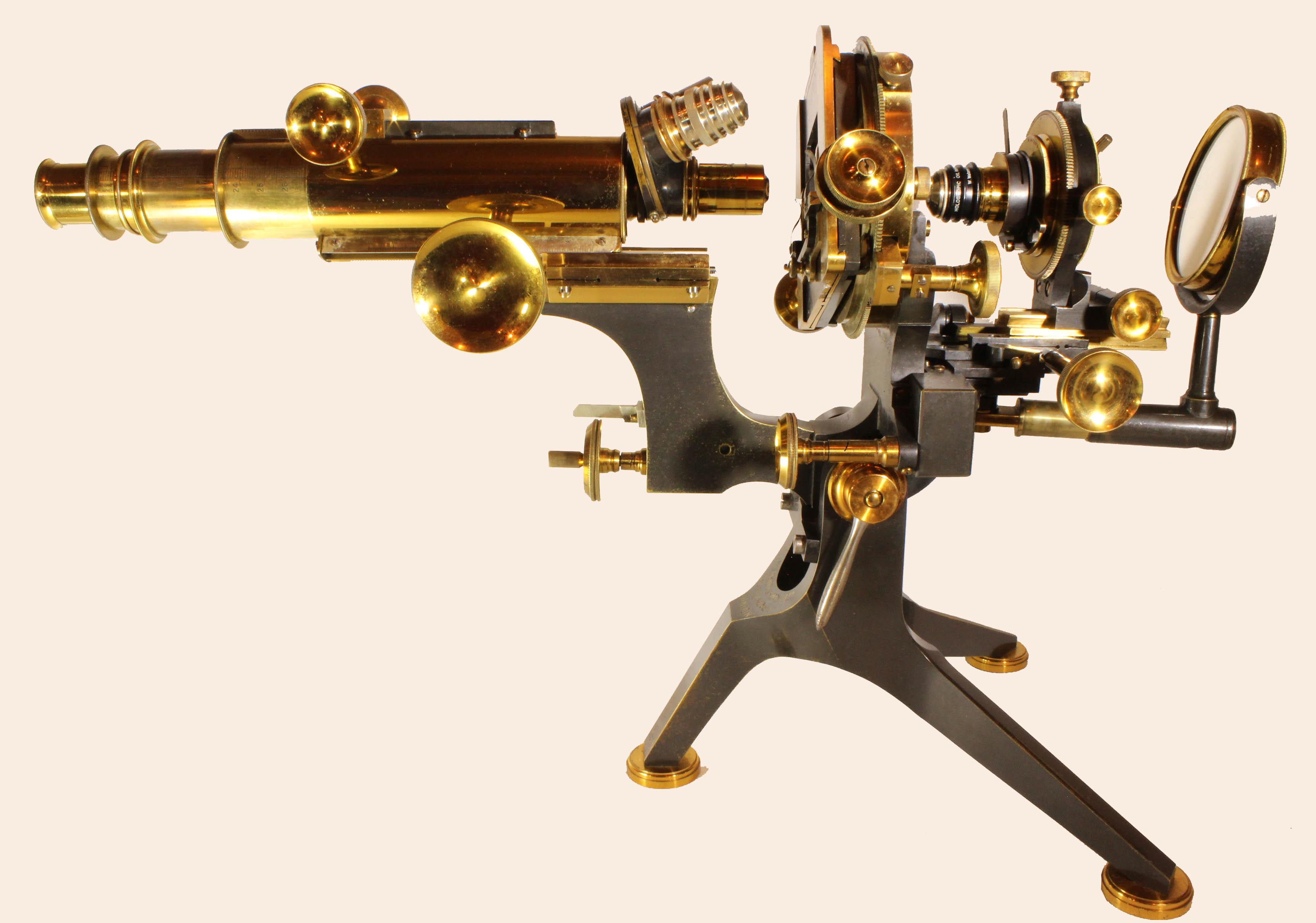
desired position on the dovetail slide. 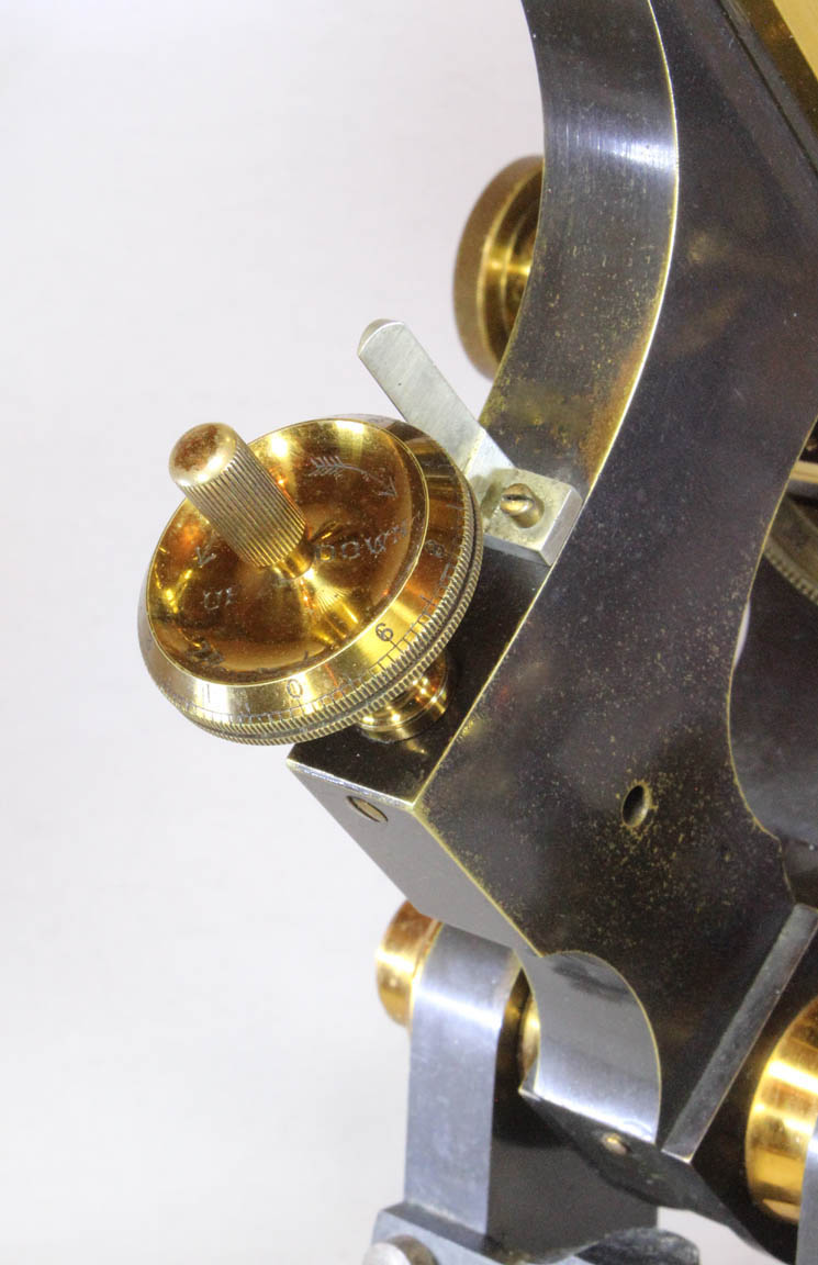 The
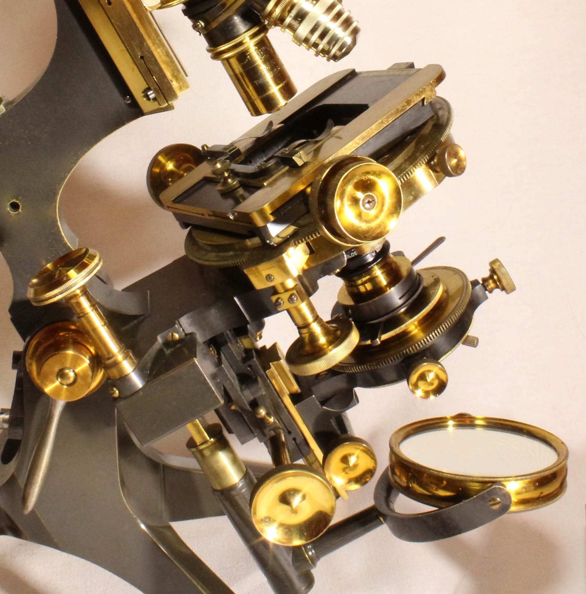
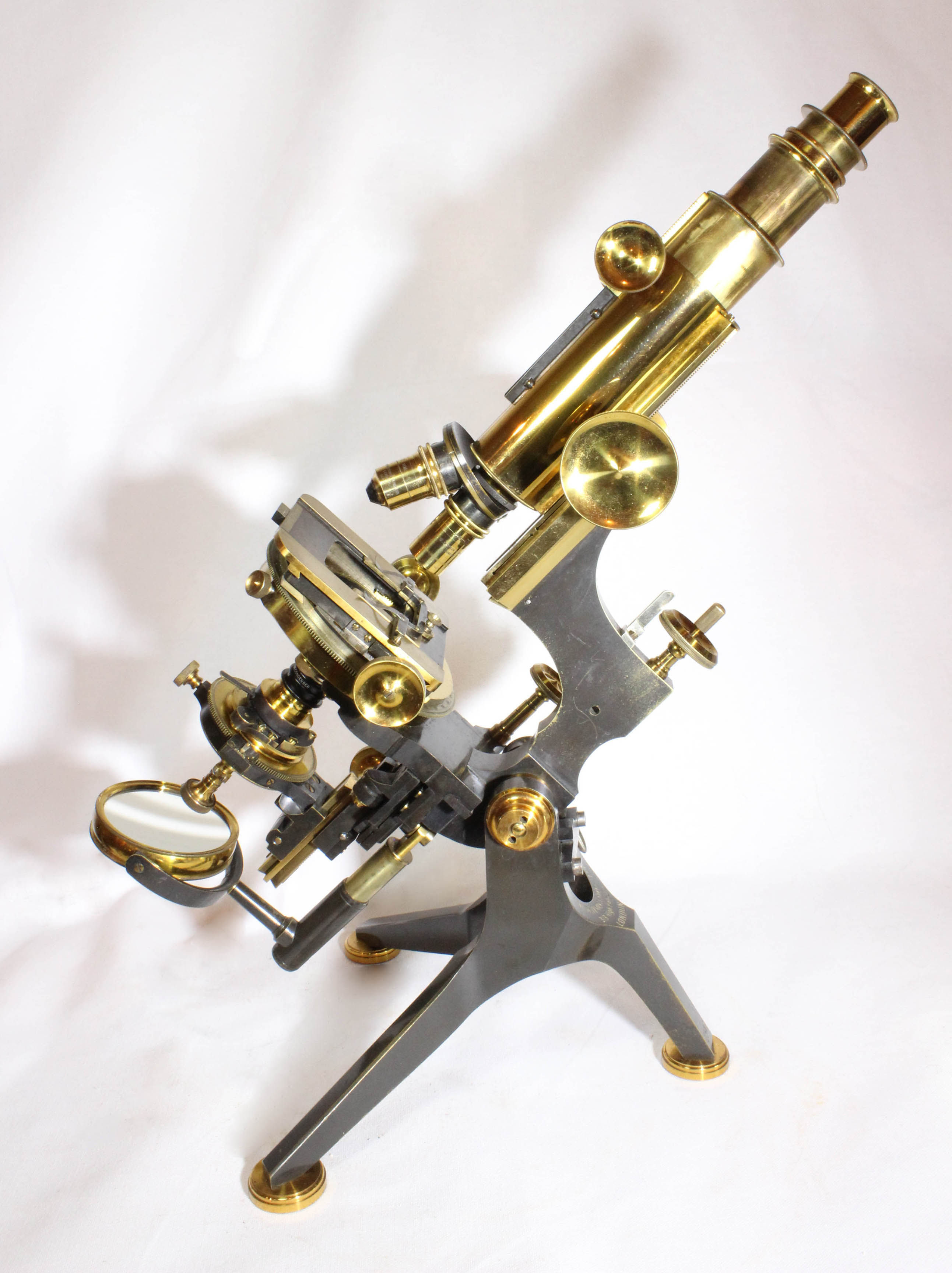
limb has a longer arm than the No. 1 Van Heurck to allow it to
position the nosepiece in the center of the extended optical axis
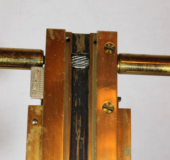
necessitated by the full rotation of the stage. Coarse focus is by
diagonal rack and spiral pinion whilst the fine focus is via a long
lever controlled from the top edge of the rear part of the arm. This
instrument is equipped with the optional two-speed 'spindle milled
head'* as the fine focus knob. The knurled lacquered brass fine focus
knob is calibrated and numbered from 0-10 with division increments of
0.1. It has arrows showing which directions of rotation lowers and
which raises the optical tube. There is a steel pointer to register
these calibrations. The instrument has a black triple nosepiece which
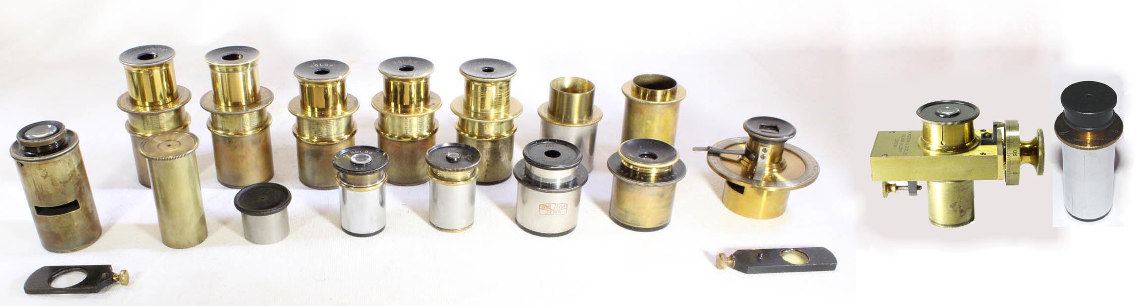
is unsigned and has no trademarks. A large number and variety of
objectives are with the instrument, and are described below with the
other accessories.
The
limb has a longer arm than the No. 1 Van Heurck to allow it to
position the nosepiece in the center of the extended optical axis
necessitated by the full rotation of the stage. Coarse focus is by
diagonal rack and spiral pinion whilst the fine focus is via a long
lever controlled from the top edge of the rear part of the arm. This
instrument is equipped with the optional two-speed 'spindle milled
head'* as the fine focus knob. The knurled lacquered brass fine focus
knob is calibrated and numbered from 0-10 with division increments of
0.1. It has arrows showing which directions of rotation lowers and
which raises the optical tube. There is a steel pointer to register
these calibrations. The instrument has a black triple nosepiece which
is unsigned and has no trademarks. A large number and variety of
objectives are with the instrument, and are described below with the
other accessories. 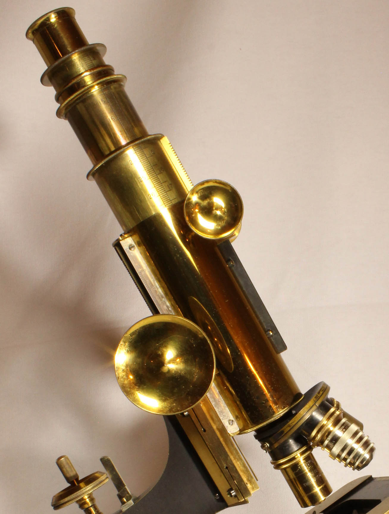
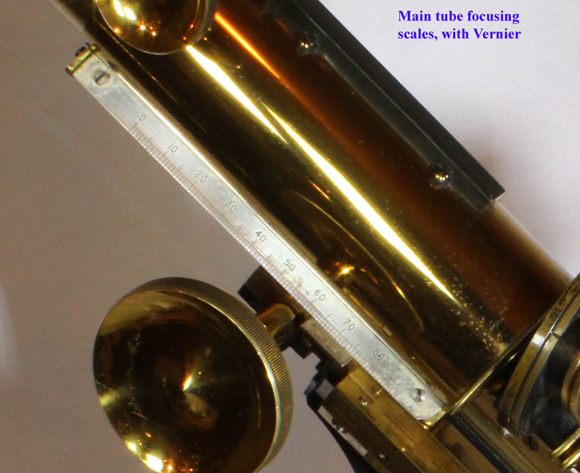
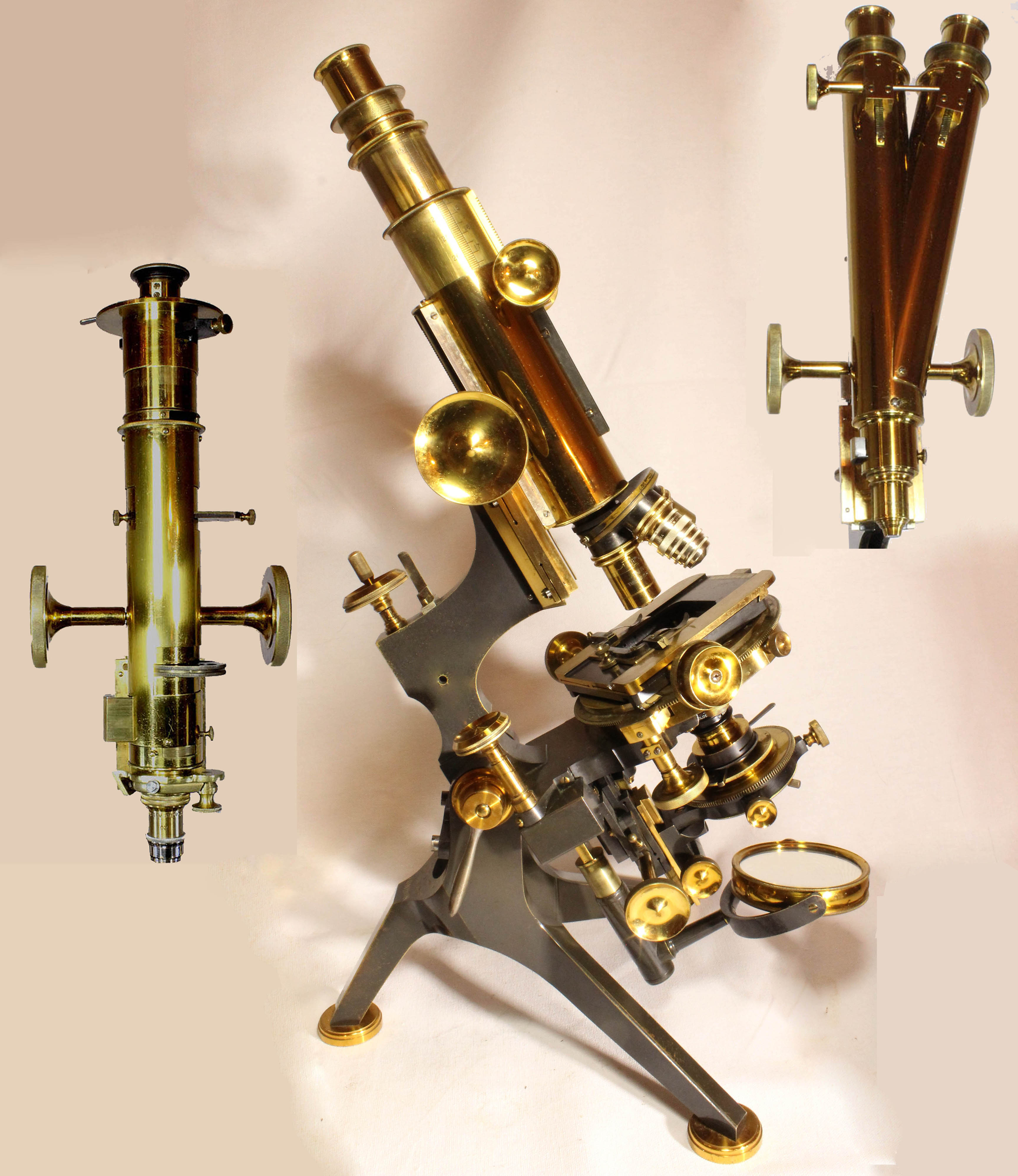
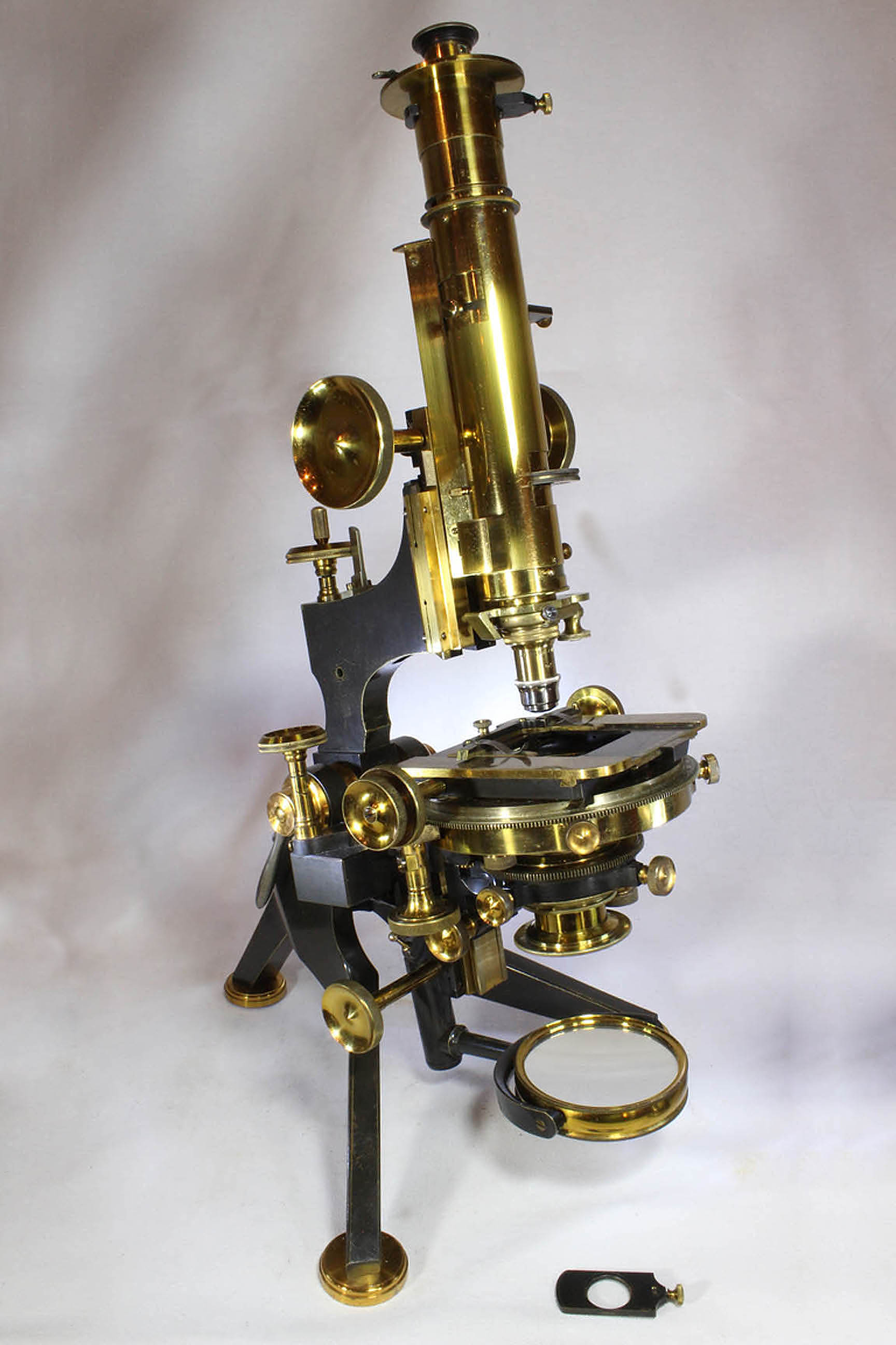
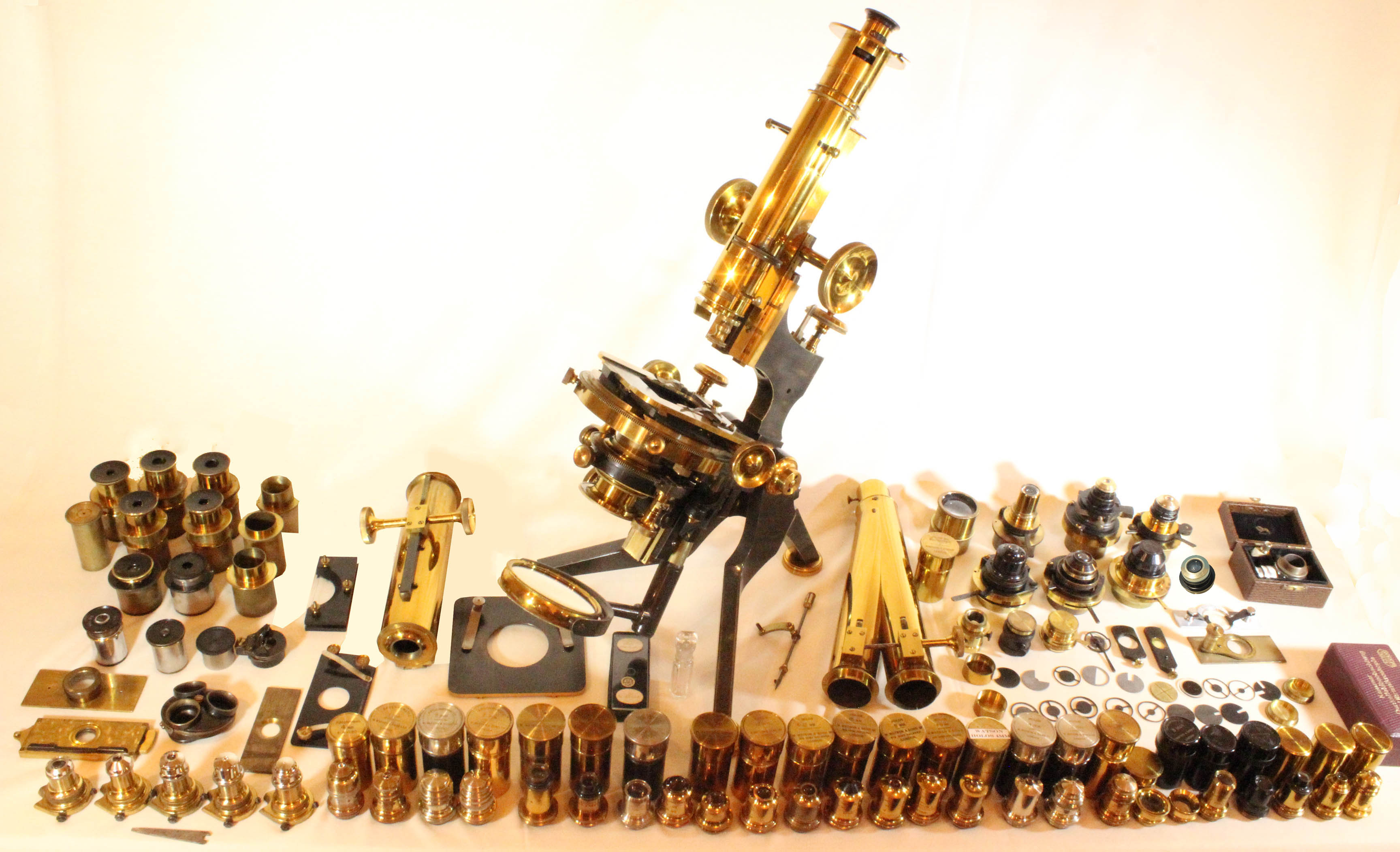
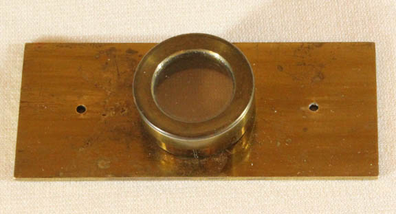
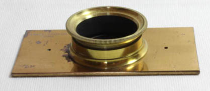
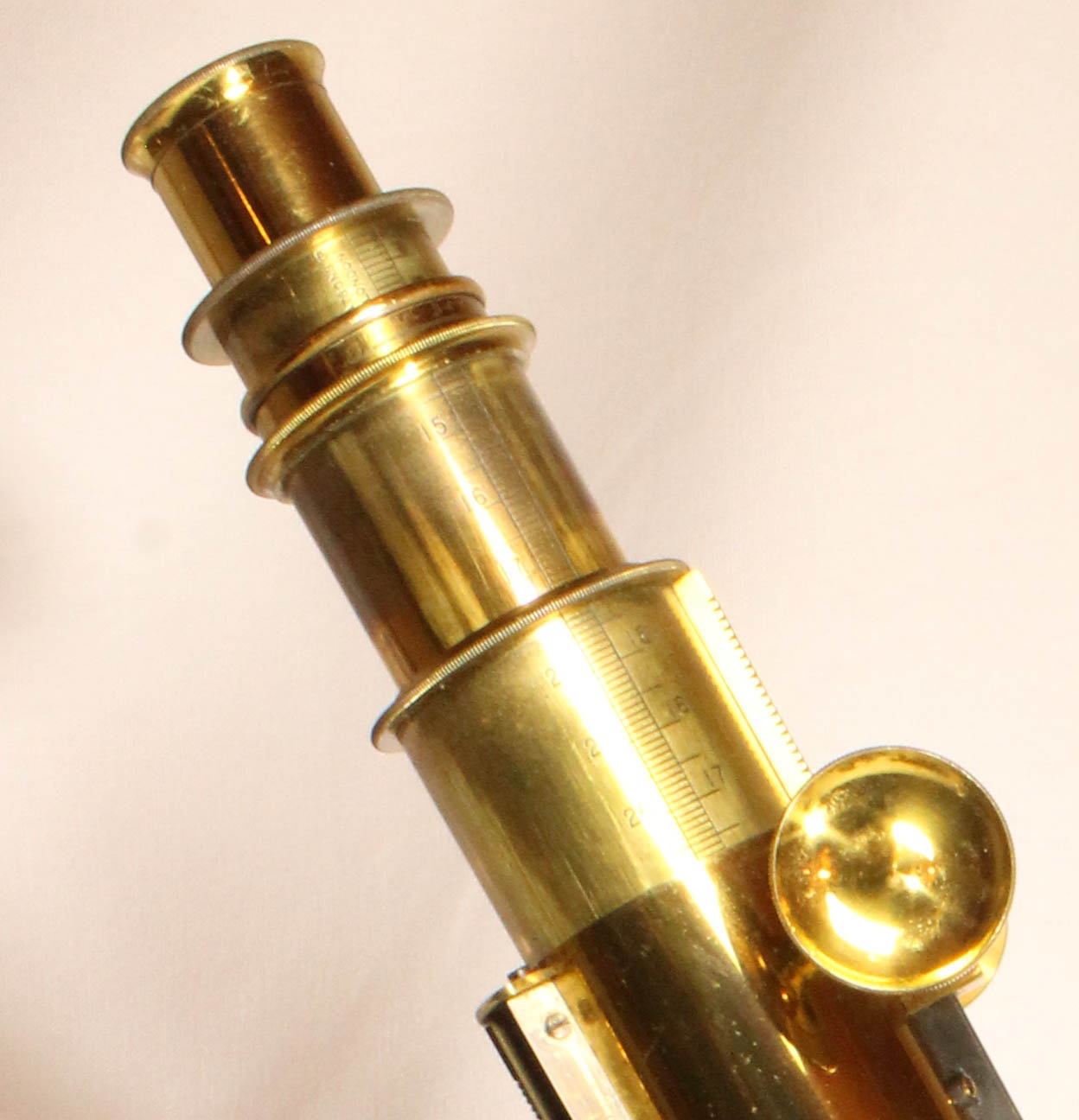 For the standard tube, as shown in
the top center picture above, and also to the left, the outermost
diameter is 1 11/16
inches (63 mm) and is about 5 inches long.
For the standard tube, as shown in
the top center picture above, and also to the left, the outermost
diameter is 1 11/16
inches (63 mm) and is about 5 inches long. 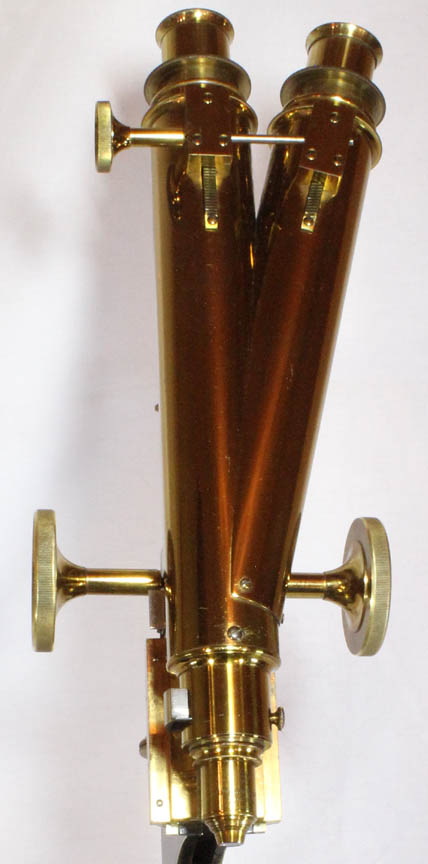 The second tube is a Wenham binocular,
with rack and pinion interocular distance adjustment. The Wenham prism
can be pushed out of the optical axis but a stop prevents accidentally
removing it completely. A disadvantage of the binocular is there is no
drawtube, and so
adjustments for tube length or coverslip thickness can only be made
with a correction collar on the objectives. The binocular tube is about
ten inches long with the interocular distance adjustment changing the
length as much as about one inch above the
end of the main tube.
The second tube is a Wenham binocular,
with rack and pinion interocular distance adjustment. The Wenham prism
can be pushed out of the optical axis but a stop prevents accidentally
removing it completely. A disadvantage of the binocular is there is no
drawtube, and so
adjustments for tube length or coverslip thickness can only be made
with a correction collar on the objectives. The binocular tube is about
ten inches long with the interocular distance adjustment changing the
length as much as about one inch above the
end of the main tube. 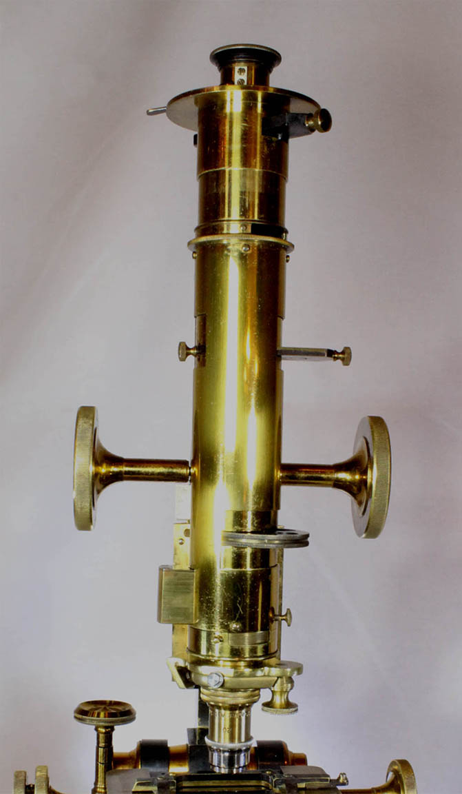 The third tube is a special petrographic tube. It
has a fixed tube length of about 7 1/2
inches (180 mm, one of the German standards). This tube is not listed
nor pictured in any Watson catalog that I have seen. It also has a
feature different from any other Watson microscope that I know of; this
is a wheel of optical elements above the
nosepiece analyzer. These consist of two different lenses both of
small diameter and long focal length, an empty opening and a first
order red retardation filter.
The third tube is a special petrographic tube. It
has a fixed tube length of about 7 1/2
inches (180 mm, one of the German standards). This tube is not listed
nor pictured in any Watson catalog that I have seen. It also has a
feature different from any other Watson microscope that I know of; this
is a wheel of optical elements above the
nosepiece analyzer. These consist of two different lenses both of
small diameter and long focal length, an empty opening and a first
order red retardation filter. 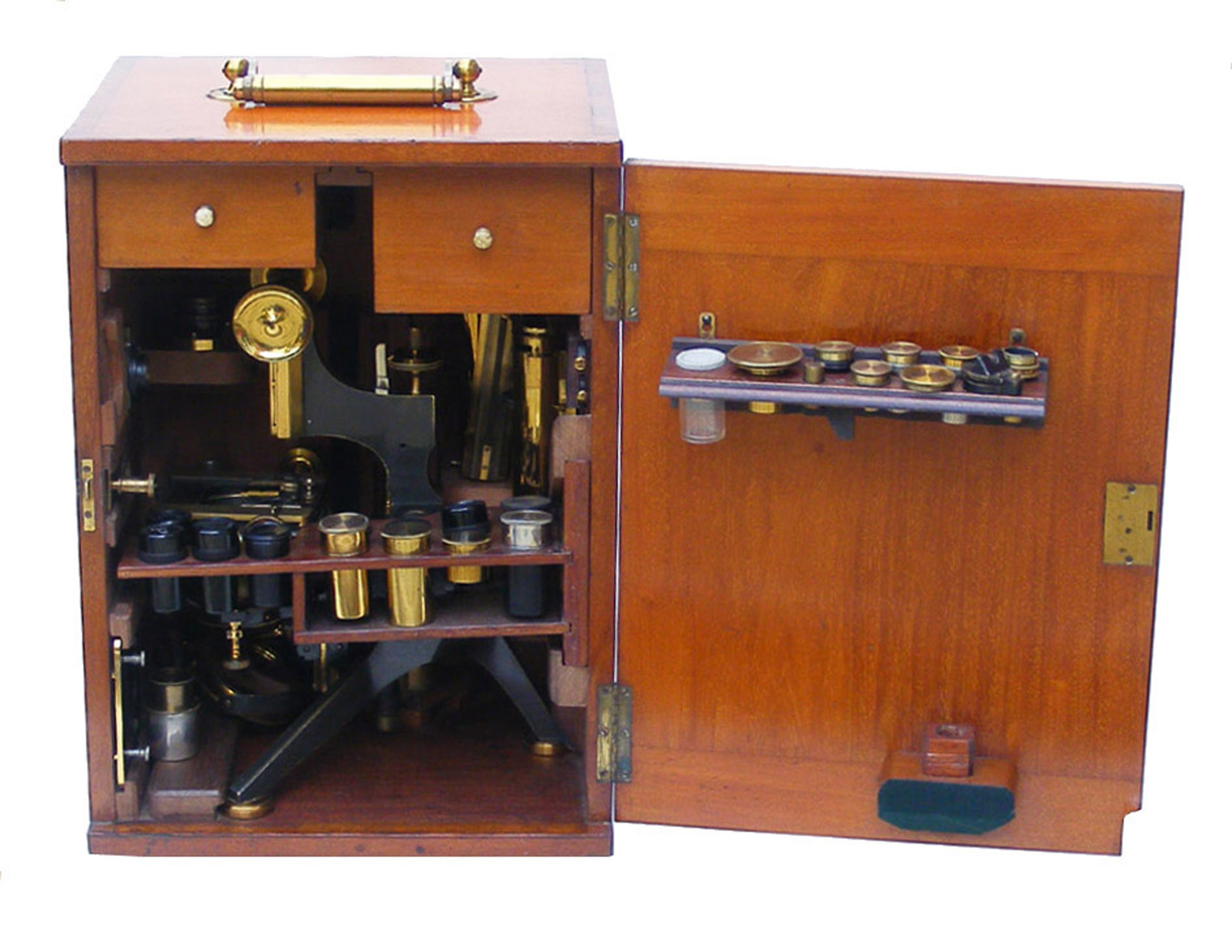 The original case
is heavy and large with a top handle but no side handles. It
has dovetail joinery. There are two original accessory drawers,with
original draw inserts remaining. The original magnification card has
apparently been removed in the past.
The inside of the case has a lot of 'furniture' added to
accommodate
some of the numerous accessories. These include individual fittings for
such things as the first order retardation plate, eyepiece micrometer, modified Rousselet compressor, the rough-work stage plate, and the three optical tubes.
Unlike some other Van Heurck cases, the microscope cannot be stored in
the case with any optical tube in place; they must be stored on the
furniture inside the case.
The original case
is heavy and large with a top handle but no side handles. It
has dovetail joinery. There are two original accessory drawers,with
original draw inserts remaining. The original magnification card has
apparently been removed in the past.
The inside of the case has a lot of 'furniture' added to
accommodate
some of the numerous accessories. These include individual fittings for
such things as the first order retardation plate, eyepiece micrometer, modified Rousselet compressor, the rough-work stage plate, and the three optical tubes.
Unlike some other Van Heurck cases, the microscope cannot be stored in
the case with any optical tube in place; they must be stored on the
furniture inside the case. 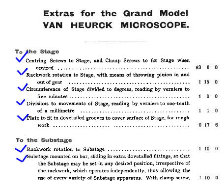
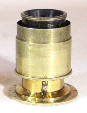
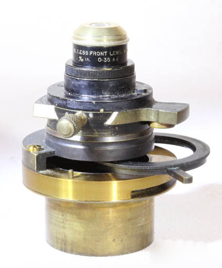 This condenser was apparently introduced by Watson about 1896 and was still being offered in the 1940s. The parachromatic condenser fits into a condenser housing that is unsigned but has the convenient feature of a Sloan-type quick change fitting allowing the optical components to be easily slide out to be exchanged for another. This housing is unsigned, but there are fittings within the case for all of its parts. Similar quick change fittings for the substage condenser can also be seen on the much later 'Swift Symposium' Model in this collection.
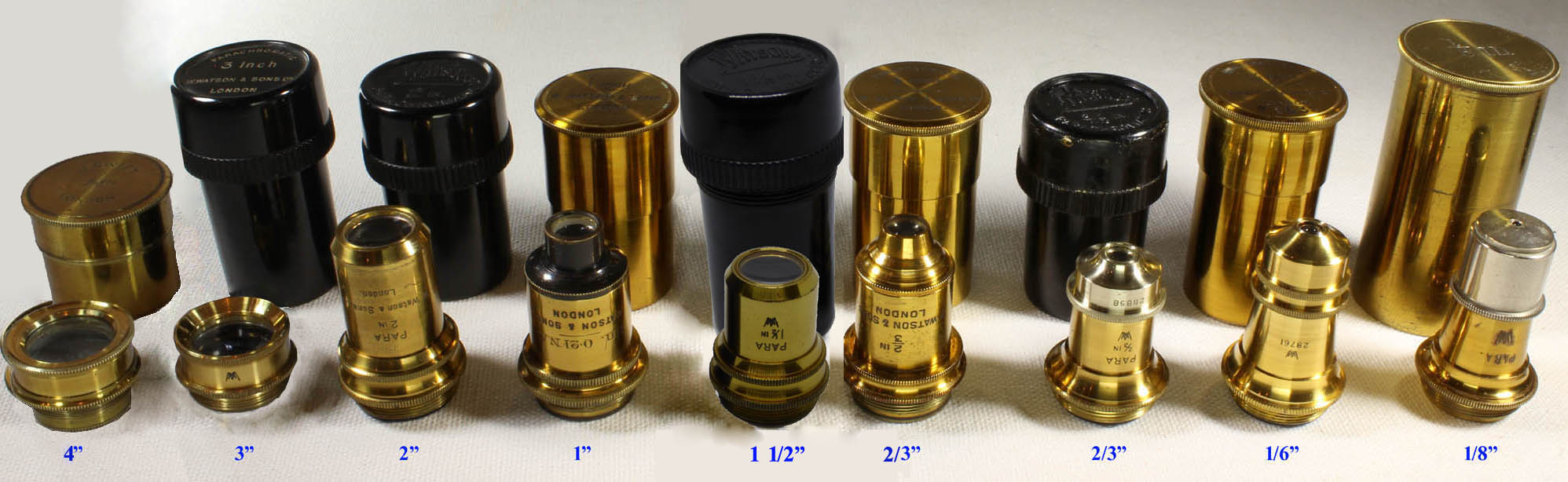
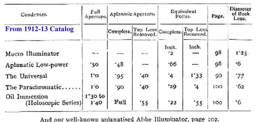
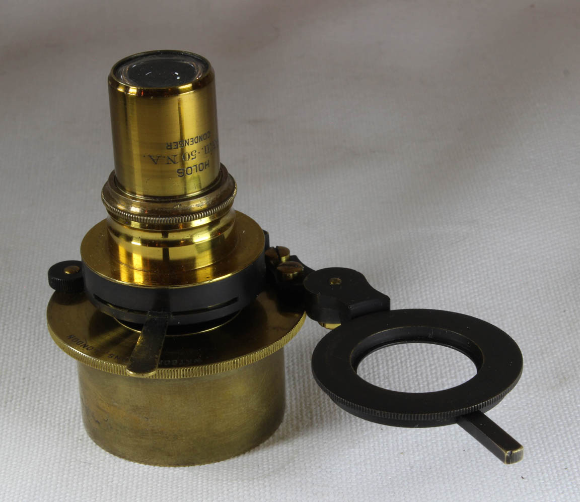 The 'Aplanatic Low Power Holoscopic' condenser is suitable
for objectives with N.A. of 0.65 or lower. It screws into a mount which can also house the 'Holoscopic Oil Immersion Condenser,' also now with the instrument. The low power Aplanatic Holos is signed:,'Holos, 2/3 in. .50 N.A.' on one side, and 'W. Watson & Sons, London on the other. It was available from no later than 1906 and continued to be offered throught the 1940s.
The 'Aplanatic Low Power Holoscopic' condenser is suitable
for objectives with N.A. of 0.65 or lower. It screws into a mount which can also house the 'Holoscopic Oil Immersion Condenser,' also now with the instrument. The low power Aplanatic Holos is signed:,'Holos, 2/3 in. .50 N.A.' on one side, and 'W. Watson & Sons, London on the other. It was available from no later than 1906 and continued to be offered throught the 1940s. 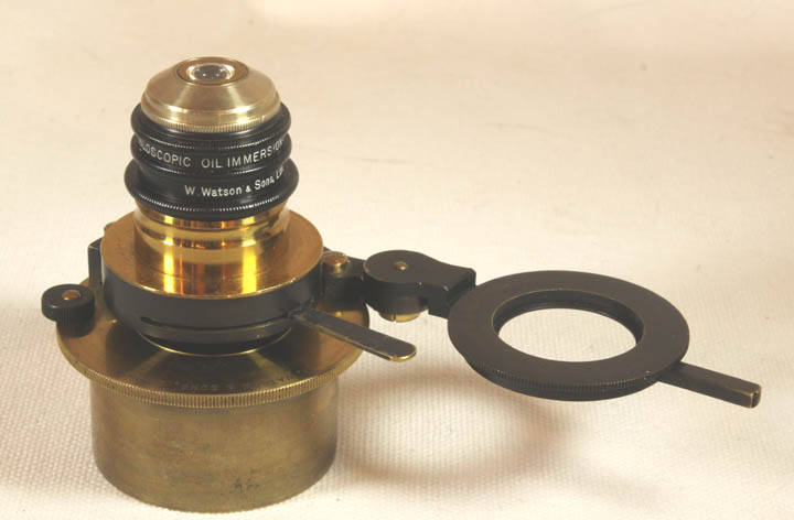 The 'Holoscopic Oil Immersion Condenser',
is suitable for use with the highest power objectives and has an
immersion front which may be removed for use with dry objectives of medium to high power. It is signed: 'HOLOSCOPIC OIL IMMERSION
CONDENSER, W. Watson & Sons Ltd
London' and also: '1.30 n.a., 3843'. It was available from no later than 1906 through the 1940s.
The 'Holoscopic Oil Immersion Condenser',
is suitable for use with the highest power objectives and has an
immersion front which may be removed for use with dry objectives of medium to high power. It is signed: 'HOLOSCOPIC OIL IMMERSION
CONDENSER, W. Watson & Sons Ltd
London' and also: '1.30 n.a., 3843'. It was available from no later than 1906 through the 1940s.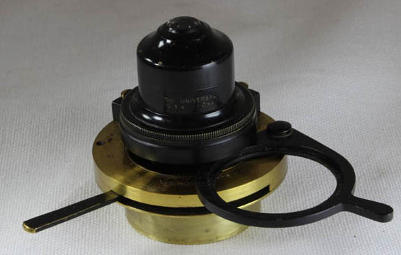 Large diameter condensers include the Universal,(shownto the left). This also fits into the same housing as the HIP condenser shown below. It was available from no later than 1906 and continued to be offered throught the 1940s.
 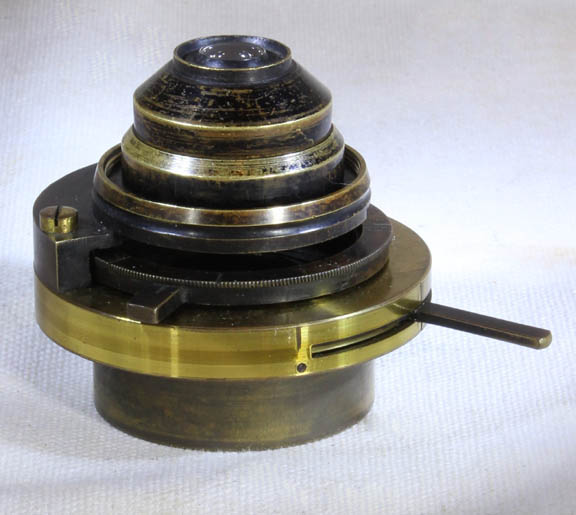 The instrument came to me with this condenser. Like the Universal, it
has a larger diameter and a removable front element. The front element
has a simple press-fit. This condenser is in a housing that has both a
slide-out filter ring and an iris diaphragm. The optical component
screws in to the housing and no part of this apparatus is signed, nor
does it match any illustrations in the Watson catalogs.
The instrument came to me with this condenser. Like the Universal, it
has a larger diameter and a removable front element. The front element
has a simple press-fit. This condenser is in a housing that has both a
slide-out filter ring and an iris diaphragm. The optical component
screws in to the housing and no part of this apparatus is signed, nor
does it match any illustrations in the Watson catalogs. 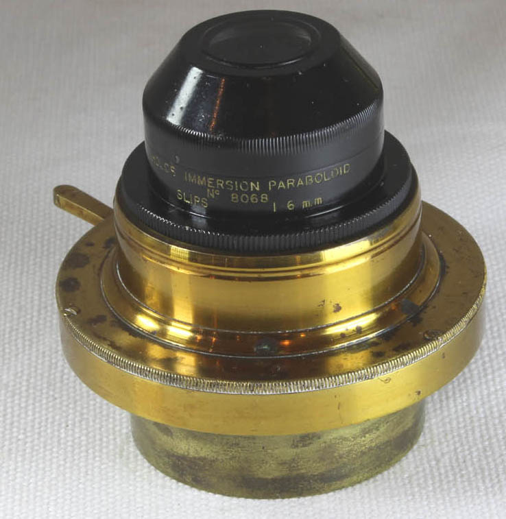 Another mount holds the 'Holos
Immersion Paraboloid' (HIP) which has an immersion front. It was available from no later than 1906 and continued to be offered throught the 1940s. The HIP can be used not only with oil immersion objectives, but also with moderate to high power dry objectives. When used with dry objectives, it still must be oiled to the bottom of the slide. In these cases it can be used with a
nosepiece iris ('Davis Shutter')
without the need for a funnel stop but for oil immersion objectives, a funnel stop would be preferred. The paraboloid is
signed:'Holos Immersion Paraboloid, No. 8068, slips 1.6 mm. The latter refers to the thickness of the slide with which the condenser is designed to work with (+/-20%). It is also signed 'W. Watson & Sons Ltd, London. The housing for the HIP has an iris but no flip out filter/stop holder like the other housings have, as this would have no purpose for a dark ground condenser. This condenser was introduced about 1909 and was reported in the JRMS of that year, part 5, p 647. The disadvantage of this dark ground condenser is that the maximum N.A. of the objective must be 0.95 or less, requiring higher N.A. objectives to be stopped down with a funnel stop, or by the use of a Davis (nosepiece) shutter.
Another mount holds the 'Holos
Immersion Paraboloid' (HIP) which has an immersion front. It was available from no later than 1906 and continued to be offered throught the 1940s. The HIP can be used not only with oil immersion objectives, but also with moderate to high power dry objectives. When used with dry objectives, it still must be oiled to the bottom of the slide. In these cases it can be used with a
nosepiece iris ('Davis Shutter')
without the need for a funnel stop but for oil immersion objectives, a funnel stop would be preferred. The paraboloid is
signed:'Holos Immersion Paraboloid, No. 8068, slips 1.6 mm. The latter refers to the thickness of the slide with which the condenser is designed to work with (+/-20%). It is also signed 'W. Watson & Sons Ltd, London. The housing for the HIP has an iris but no flip out filter/stop holder like the other housings have, as this would have no purpose for a dark ground condenser. This condenser was introduced about 1909 and was reported in the JRMS of that year, part 5, p 647. The disadvantage of this dark ground condenser is that the maximum N.A. of the objective must be 0.95 or less, requiring higher N.A. objectives to be stopped down with a funnel stop, or by the use of a Davis (nosepiece) shutter. 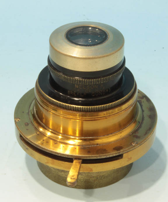 About 1925, another dark ground condenser, designed by the eminent microscopist E.M. Nelson was released by Watson as
 Nelson's Cassegrain Dark Ground Illuminator. This condenser, which fits the same housing as the Holos Immersion Paraboloid, was also called
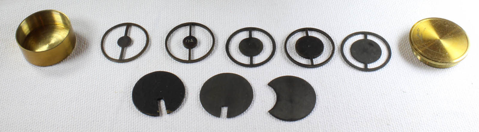
Nelson's Reflex Condenser. This illuminator was designed for slides of 1 to 1.2 mm thickness. It was supplied with 2 different diameter stops, although only one labeled
16is present with this example. This condenser has the advantage of allowing the full N.A. of oil immersion objectives to be used with N.A. up to 1.40. This type of high power dark ground condenser is much less complex and easier to manufacture than the cardioid type*, though the latter is usually optically superior.
 Another illuminator is a Zeiss prism type of vertical illuminator with oxidized-black finish. This illuminator is no longer with the microscope,since the combined illuminator in the next entry has the option of using a prism included in the kit.
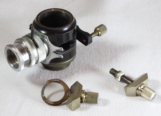 Later the Watson 'Combined Vertical Illuminator' set was offered and is also with this instrument. The Watson 'Combined Vertical Illuminator' was first offered by Watson after 1921, and is shown in the 1923 catalog (thanks to Dr Joe Zeligs for this information). The Combination illuminator came in a signed case, providing the option of a tiny prism or coverslip for reflecting the illuminating light beam.
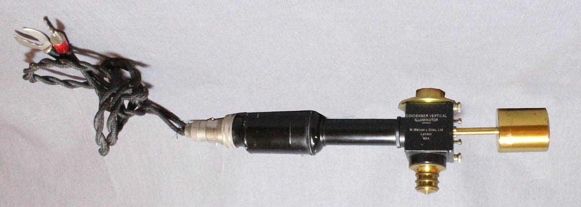
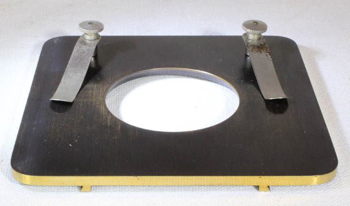 There is a also an accessory stage plate 'for rough
work' which slides in from the front of the stage into the
dovetail slots which also accept the slide support bar.
There is a also an accessory stage plate 'for rough
work' which slides in from the front of the stage into the
dovetail slots which also accept the slide support bar. 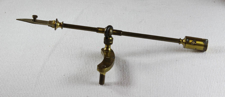 A Watson 'Best' stage forceps
with curving support also accompanies the instrument.
A Watson 'Best' stage forceps
with curving support also accompanies the instrument. 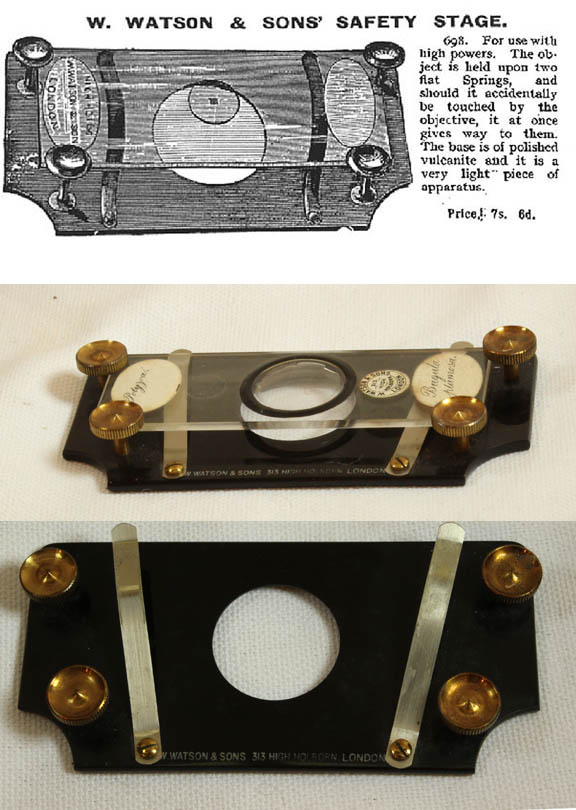 Another stage accessory is
the Watson 'Safety Stage'.
This very uncommon accessory is made of hard rubber ('Vulcanite'), with
some lacquered brass parts and 'stage clips', which gently push up on the
slide to hold it against the brass retaining knobs. This takes
advantage of the upward curving center of the stage clips to push up on
the bottom of the slide. Should the
user accidentally force the nosepiece and objective onto the slide itself, the springy stage clips give way, preventing damage to both slide and objective. It is signed in white letters on the Vulcanite: 'W
WATSON & sons 313 HIGH HOLBORN, LONDON'. This stage was offered in the catalogs from 1885 to 1906.
Another stage accessory is
the Watson 'Safety Stage'.
This very uncommon accessory is made of hard rubber ('Vulcanite'), with
some lacquered brass parts and 'stage clips', which gently push up on the
slide to hold it against the brass retaining knobs. This takes
advantage of the upward curving center of the stage clips to push up on
the bottom of the slide. Should the
user accidentally force the nosepiece and objective onto the slide itself, the springy stage clips give way, preventing damage to both slide and objective. It is signed in white letters on the Vulcanite: 'W
WATSON & sons 313 HIGH HOLBORN, LONDON'. This stage was offered in the catalogs from 1885 to 1906. 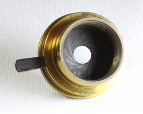 The 'Davis Shutter' is
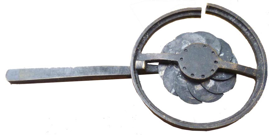
a nosepiece iris diaphragm. It can be used to
increase the depth of focus, and also for dark field work, except with
highest powers where a funnel stop* would be preferred. It was first
suggested by Dr Royston-Pigott in 1869 for erroneous purposes, however
it was first noted for its usefulness for 'increasing penetration' as
described above on page 262 of the JRMS of 1882. When the
shutter
is used to increase depth of field, resolution is reduced.
This instrument has one unsigned and another signed by Swift.
The 'Davis Shutter' is
a nosepiece iris diaphragm. It can be used to
increase the depth of focus, and also for dark field work, except with
highest powers where a funnel stop* would be preferred. It was first
suggested by Dr Royston-Pigott in 1869 for erroneous purposes, however
it was first noted for its usefulness for 'increasing penetration' as
described above on page 262 of the JRMS of 1882. When the
shutter
is used to increase depth of field, resolution is reduced.
This instrument has one unsigned and another signed by Swift.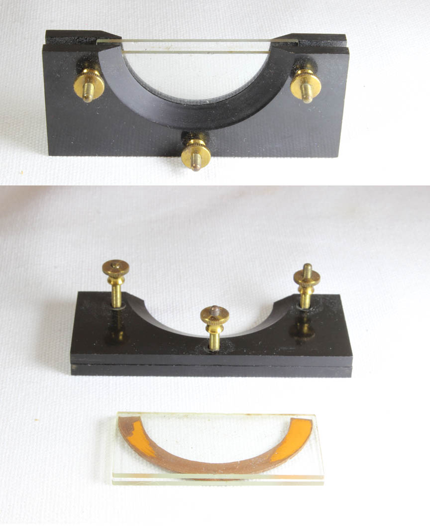 A 'Botterhill Trough'
(left) is also among the accessories. Viewing moving organisms with a microscope has always been a challenge. Various types of apparatus have been devised to contain and/or restrain such organisms. They vary from
a simple small container to more sophisticated compressoria. One type of container is a trough and the type invented by Botterhill was offered by Watson from 1893 through the early 20th century. The Botterhill trough was first reported in the JRMS Volume 3, part 1, pages 148-149 in 1880 but was not offered in the 1883 Watson catalog. In the 1880 report it specified the outer trough plates be
made of brass, but they were soon offered made of Vulcanite as well, and the 1893 listings by Watson offered them in Vulcanite. The apparatus consists of two pieces of thin glass separated by a piece of 'India Rubber' and these resting inside the container of two Vulcanite plates each with a circular cutout and beveled edge. Three screws apply pressure to keep
the apparatus water-tight. The thickness of the rubber spacer between the glass plates can be varied to
suit the thickness of the animal being studied. The apparatus can be disassembled easily to allow the plates and rubber to be cleaned or replaced. According to George Davis, in 'Practical Microscopy of 1889, this device was first manufactured by Thomson and Capper of Liverpool, who also were the first to make Botterhill's
'Microscopic Life Slide' an example of which is also in this collection. The Life slide was noted in the 'English Mechanic and World of Science of June 3, 1881
page 298.
A 'Botterhill Trough'
(left) is also among the accessories. Viewing moving organisms with a microscope has always been a challenge. Various types of apparatus have been devised to contain and/or restrain such organisms. They vary from
a simple small container to more sophisticated compressoria. One type of container is a trough and the type invented by Botterhill was offered by Watson from 1893 through the early 20th century. The Botterhill trough was first reported in the JRMS Volume 3, part 1, pages 148-149 in 1880 but was not offered in the 1883 Watson catalog. In the 1880 report it specified the outer trough plates be
made of brass, but they were soon offered made of Vulcanite as well, and the 1893 listings by Watson offered them in Vulcanite. The apparatus consists of two pieces of thin glass separated by a piece of 'India Rubber' and these resting inside the container of two Vulcanite plates each with a circular cutout and beveled edge. Three screws apply pressure to keep
the apparatus water-tight. The thickness of the rubber spacer between the glass plates can be varied to
suit the thickness of the animal being studied. The apparatus can be disassembled easily to allow the plates and rubber to be cleaned or replaced. According to George Davis, in 'Practical Microscopy of 1889, this device was first manufactured by Thomson and Capper of Liverpool, who also were the first to make Botterhill's
'Microscopic Life Slide' an example of which is also in this collection. The Life slide was noted in the 'English Mechanic and World of Science of June 3, 1881
page 298. 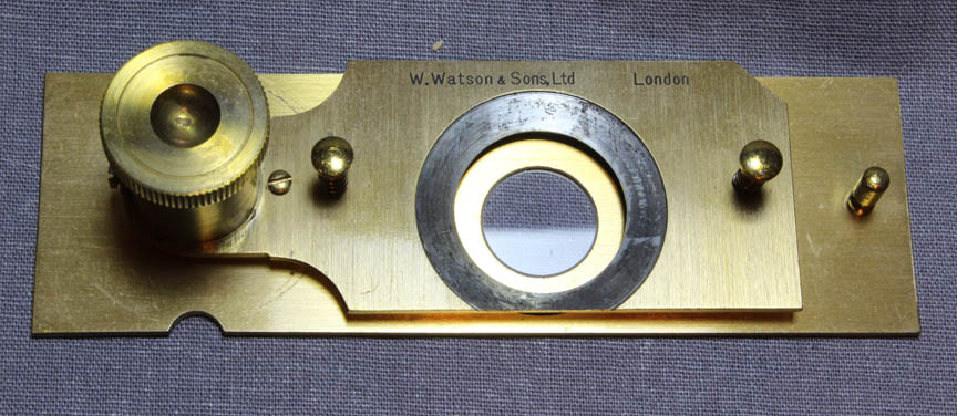 This is a Watson variation of Rousselet compressor, which was described by Rousselet in the 1893 volume of the JRMS. It illustrates the Watson modifications on the original Rousselet design. As shown here, it uses quick release fittings to hold the upper glass in place. Although this made changing the upper cover glass fast and easy, it was a distinct disadvantage over the method of gluing the top glass on, which then forms a seal, so that fluids like immersion oil would not seep under the top cover slip from above. (see Rousselet, CF, A Description of the Rousselet Compressorium, JQMC vol IX, 1904-1906 p 137-8). Please click on the image for more details and images.
 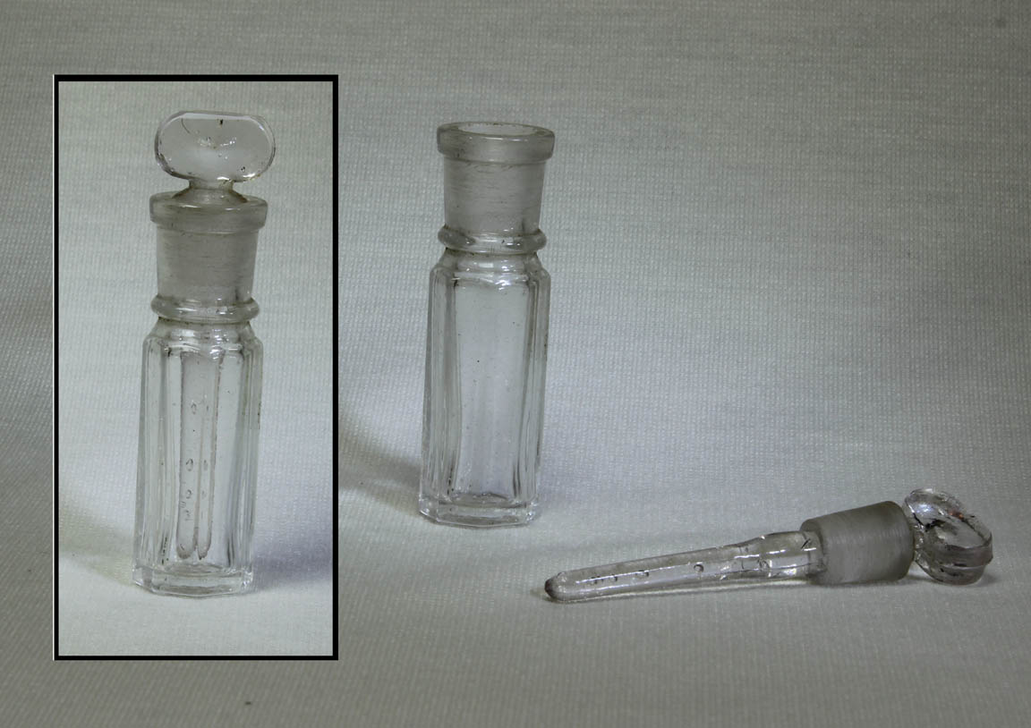 This little bottle for immersion oil fits in a wooden cup on the door
of the case.
This little bottle for immersion oil fits in a wooden cup on the door
of the case. 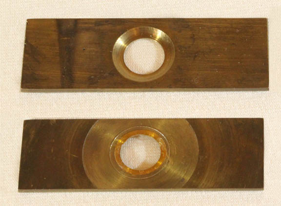 Depression
slides, usually made of solid glass now, were at one time made mostly
of brass. They are used to study a small amount of liquid such as pond
water, but unlike the compressor and some live boxes, have no mechanism
to immobilize any swimming creatures. Another disadvantage,
if used with a coverslip, is lack of facility of adding
liquid as the original is evaporating. Botterhill's life
slide is a superior design in that respect.
Depression
slides, usually made of solid glass now, were at one time made mostly
of brass. They are used to study a small amount of liquid such as pond
water, but unlike the compressor and some live boxes, have no mechanism
to immobilize any swimming creatures. Another disadvantage,
if used with a coverslip, is lack of facility of adding
liquid as the original is evaporating. Botterhill's life
slide is a superior design in that respect.
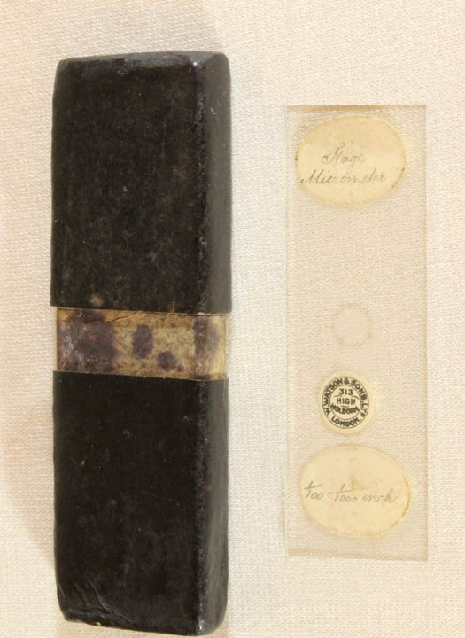 This stage micrometer is
used to calibrate the eyepiece micrometer for each objective.
This stage micrometer is
used to calibrate the eyepiece micrometer for each objective.
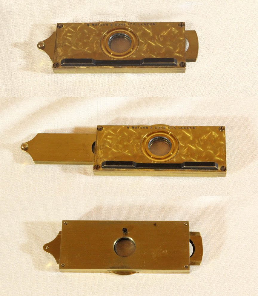 This
'Mica Selenite Stage' provides three different selenites in
a slider with a rotatable mica disc above controlled by the knurled
knob in center. This device would reveal a wide variation in colors of
polarized objects-a very entertaining accessory. Click on the image to see the effects of this accessory.
This
'Mica Selenite Stage' provides three different selenites in
a slider with a rotatable mica disc above controlled by the knurled
knob in center. This device would reveal a wide variation in colors of
polarized objects-a very entertaining accessory. Click on the image to see the effects of this accessory.
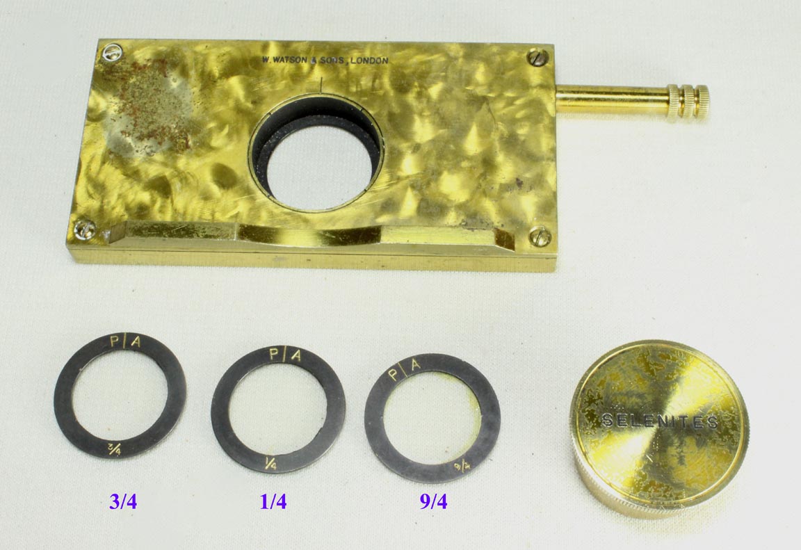 This 'Selenite Stage' was a bit more expensive than the 'Mica-Selenite Stage' as it uses a geared mechanism to rotate the central well. The selenites were provided individually and as such could be used singly or combined. This accessory was offered by Watson for over sixty years! It gives a slightly wider variety in choice of effects than the Mica-Selenite Stage. Click on the image to see the effects of this accessory.
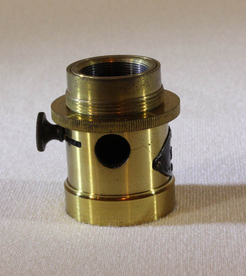
 This
is a livebox, intended to allow observation of living specimens. It consists of a short tube or barrel, the top of which is covered with glass. A liquid or solid specimen can be placed here. The cap, with a glass top can then be pushed down over this barrel of the slide to contain the specimen, either with no pressure or with some degree of pressure as desired. The degree of pressure applied cannot be varied as precisely
as it can be in the modified Rousselet compressor shown above. This livebox has the typical small holes to either side of the cylinder, also found on other Watson liveboxes.
Rousselet also popularized an improved livebox(though it was invented much earlier), and Watson was among those who made them (see next entry).
This
is a livebox, intended to allow observation of living specimens. It consists of a short tube or barrel, the top of which is covered with glass. A liquid or solid specimen can be placed here. The cap, with a glass top can then be pushed down over this barrel of the slide to contain the specimen, either with no pressure or with some degree of pressure as desired. The degree of pressure applied cannot be varied as precisely
as it can be in the modified Rousselet compressor shown above. This livebox has the typical small holes to either side of the cylinder, also found on other Watson liveboxes.
Rousselet also popularized an improved livebox(though it was invented much earlier), and Watson was among those who made them (see next entry).
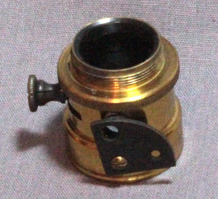
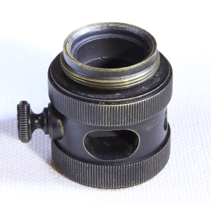
 This
is a livebox, intended to allow observation of living specimens, similar to the preceding entry. This later version was popularized about 1887 by Charles Rousselet, FRMS, though it turns out it was invented much earlier, by Blankley as reported in the English Mechanic and World of Science, No. 305, Jan 27, 1871, p 437. It is similar in some ways to the Varley livebox. In this variation, the lower glass is a raised 'tablet' with chamfered edges at the bottom of the cylinder. The upper portion or 'cap', instead of fitting around the outside of the bottom cylinder fits inside it. Also instead of the glass on the top of the second cylinder, it is on the bottom, so as to meet the tablet. Furthermore this upper cylinder is actually a double cylinder with its inside part threaded to the outer part, thus holding the glass in place. This allows the glass to be changed in or out without the need for glue. This livebox has two holes similar to the preceding example but this one is signed: 'W. Watson & Sons Ltd., London'. This would date this to after 1908. This design is like Rousselet's form, not the early twentieth century modification by Merlin. These types of live boxes were also made by Smith, Ross, Swift, and likely others. For more images of this livebox, please click on the image. An example of this type of livebox sold by Swift around 1877 is on this site.
This
is a livebox, intended to allow observation of living specimens, similar to the preceding entry. This later version was popularized about 1887 by Charles Rousselet, FRMS, though it turns out it was invented much earlier, by Blankley as reported in the English Mechanic and World of Science, No. 305, Jan 27, 1871, p 437. It is similar in some ways to the Varley livebox. In this variation, the lower glass is a raised 'tablet' with chamfered edges at the bottom of the cylinder. The upper portion or 'cap', instead of fitting around the outside of the bottom cylinder fits inside it. Also instead of the glass on the top of the second cylinder, it is on the bottom, so as to meet the tablet. Furthermore this upper cylinder is actually a double cylinder with its inside part threaded to the outer part, thus holding the glass in place. This allows the glass to be changed in or out without the need for glue. This livebox has two holes similar to the preceding example but this one is signed: 'W. Watson & Sons Ltd., London'. This would date this to after 1908. This design is like Rousselet's form, not the early twentieth century modification by Merlin. These types of live boxes were also made by Smith, Ross, Swift, and likely others. For more images of this livebox, please click on the image. An example of this type of livebox sold by Swift around 1877 is on this site.
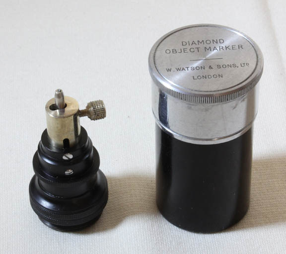 This device is an 'object marker.' It is used to inscribe a circle around an area of interest on a slide or coverslip on a slide. It makes use of a small diamond. In use, the microscopist centers the area of interest, and then replaces the objective with this device. It is spring loaded. As the optical tube of the microscope is lowered onto the slide, the spring applies just enough pressure. The user rotates the diamond via the knurled ring. A small knob adjusts the size of circle the marker produces; it is difficult to use the device if a very small diameter circle is chosen. This device was first invented by Leitz in the first decade of the twentieth century, and then copied by Watson. It is not listed in any Watson Catalog that I could find. Another form of object marker also fitting on the nosepiece, was used to simply stamp an area with ink. This stamping device was devised earlier than the diamond marker, and obviously made a circle that was not as durable, though more easily seen with the naked eye than the diamond mark. In the twentieth century, Nikon produced a modern form of stamping object marker which actually had an ink resevoir.
 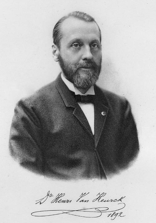 The
famous Belgian microscopist, Henri Van Heurck(1839-1909) was the
manager of his family business manufacturing paints and varnishes. He became famous as a botanist, expert microscopist, photomicrographer, and especially diatomist. More than one diatom species is named in his
honor. The basic plan for the Van Heurck stand was based on the earlier
Edinburgh stand, a model devised with the advice of an Edinburgh
professor. For more historical information about the various models of
the Edinburgh microscope see the Edinburgh
B page and the Edinburgh
H page.
The
famous Belgian microscopist, Henri Van Heurck(1839-1909) was the
manager of his family business manufacturing paints and varnishes. He became famous as a botanist, expert microscopist, photomicrographer, and especially diatomist. More than one diatom species is named in his
honor. The basic plan for the Van Heurck stand was based on the earlier
Edinburgh stand, a model devised with the advice of an Edinburgh
professor. For more historical information about the various models of
the Edinburgh microscope see the Edinburgh
B page and the Edinburgh
H page.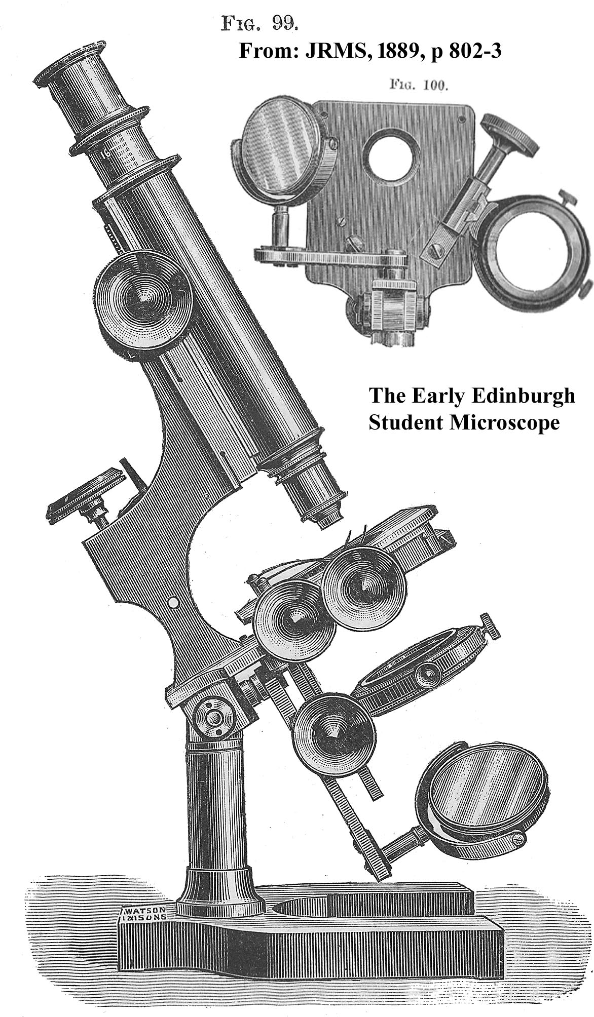 Watson
& Sons had been making microscopes since about 1874. For some time in their early production, their microscopes were similar to other contemporary makers, but soon they started to produce a variety of interesting designs, including their own variation of the Walter
Bulloch Biological No. 2, and also a version loosely based on Wale's New Working Microscope. In 1887, Dr Edington, a Lecturer in Bacteriology from the University of Edinburgh, suggested the first form of the Edinburgh stand; according to Watson's delivery records, the first example was sold on November 29, 1887. This stand was the inspiration for the Van Heurck stand, and like the Van Heurck, started
out with a continental foot, but was soon ordered more often with a tripod foot. Like the Van Heurck, it was improved progressively over the
years. This culminated in the Edinburgh 'D' and 'H' models, (an example of 'D' is shown to the left), which had most of the basic features of the (later) 'Royal' model.
In fact, when the Royal
was first introduced, it was actually slightly smaller than the Edinburgh H. The various
Edinburgh stands were at first indicated by the numbers 1,2,3, and 4, but by
1890, the letters A,B,C and D were used.
Watson
& Sons had been making microscopes since about 1874. For some time in their early production, their microscopes were similar to other contemporary makers, but soon they started to produce a variety of interesting designs, including their own variation of the Walter
Bulloch Biological No. 2, and also a version loosely based on Wale's New Working Microscope. In 1887, Dr Edington, a Lecturer in Bacteriology from the University of Edinburgh, suggested the first form of the Edinburgh stand; according to Watson's delivery records, the first example was sold on November 29, 1887. This stand was the inspiration for the Van Heurck stand, and like the Van Heurck, started
out with a continental foot, but was soon ordered more often with a tripod foot. Like the Van Heurck, it was improved progressively over the
years. This culminated in the Edinburgh 'D' and 'H' models, (an example of 'D' is shown to the left), which had most of the basic features of the (later) 'Royal' model.
In fact, when the Royal
was first introduced, it was actually slightly smaller than the Edinburgh H. The various
Edinburgh stands were at first indicated by the numbers 1,2,3, and 4, but by
1890, the letters A,B,C and D were used. 
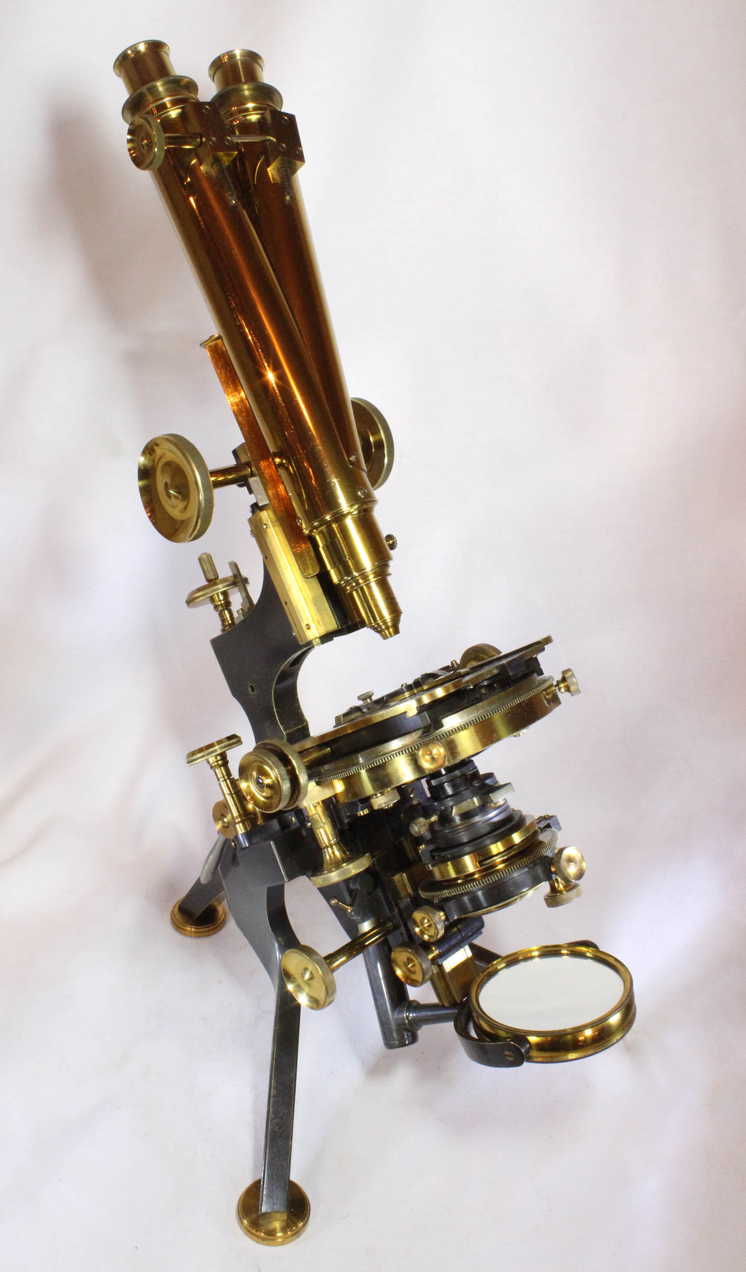
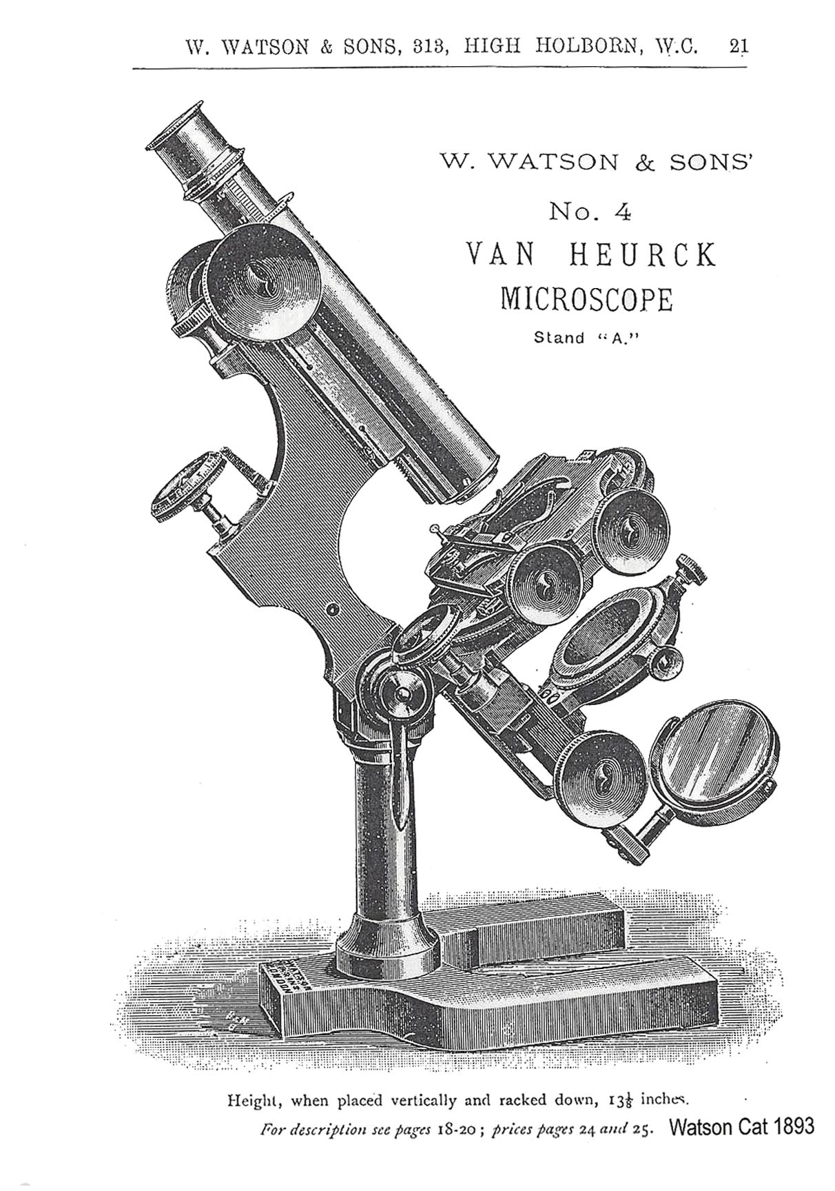 This microscope was pictured in the first edition of Van Heurck's book also dated 1891. This first version is identical to the 'Watson No. 4 Van Heurck Stand A' seen in the 1893 catalog. Study of the illustrations shows that this initial Van Heurck differed from the original Edinburgh mainly in two features-the fine adjustment for the substage, and the ability to
rotate the entire mechanical stage. Van Heurck preferred to do all of his photomicrography with a vertically oriented microscope which is why he preferred his microscope to be made with a continental
This microscope was pictured in the first edition of Van Heurck's book also dated 1891. This first version is identical to the 'Watson No. 4 Van Heurck Stand A' seen in the 1893 catalog. Study of the illustrations shows that this initial Van Heurck differed from the original Edinburgh mainly in two features-the fine adjustment for the substage, and the ability to
rotate the entire mechanical stage. Van Heurck preferred to do all of his photomicrography with a vertically oriented microscope which is why he preferred his microscope to be made with a continental horseshoefoot and supported on a single pillar, so as not to interfere with substage adjustments during the, (then) delicate operation, of photomicrography with high power objectives. At the same time, many others preferred the horizontal position for photography. For this reason, his stand was also offered with the more stable English tripod foot which provided a much more stable stand for photography in the horizontal position. Many more examples with an English tripod exist than with the horseshoe foot, as the tripod quickly became more popular.
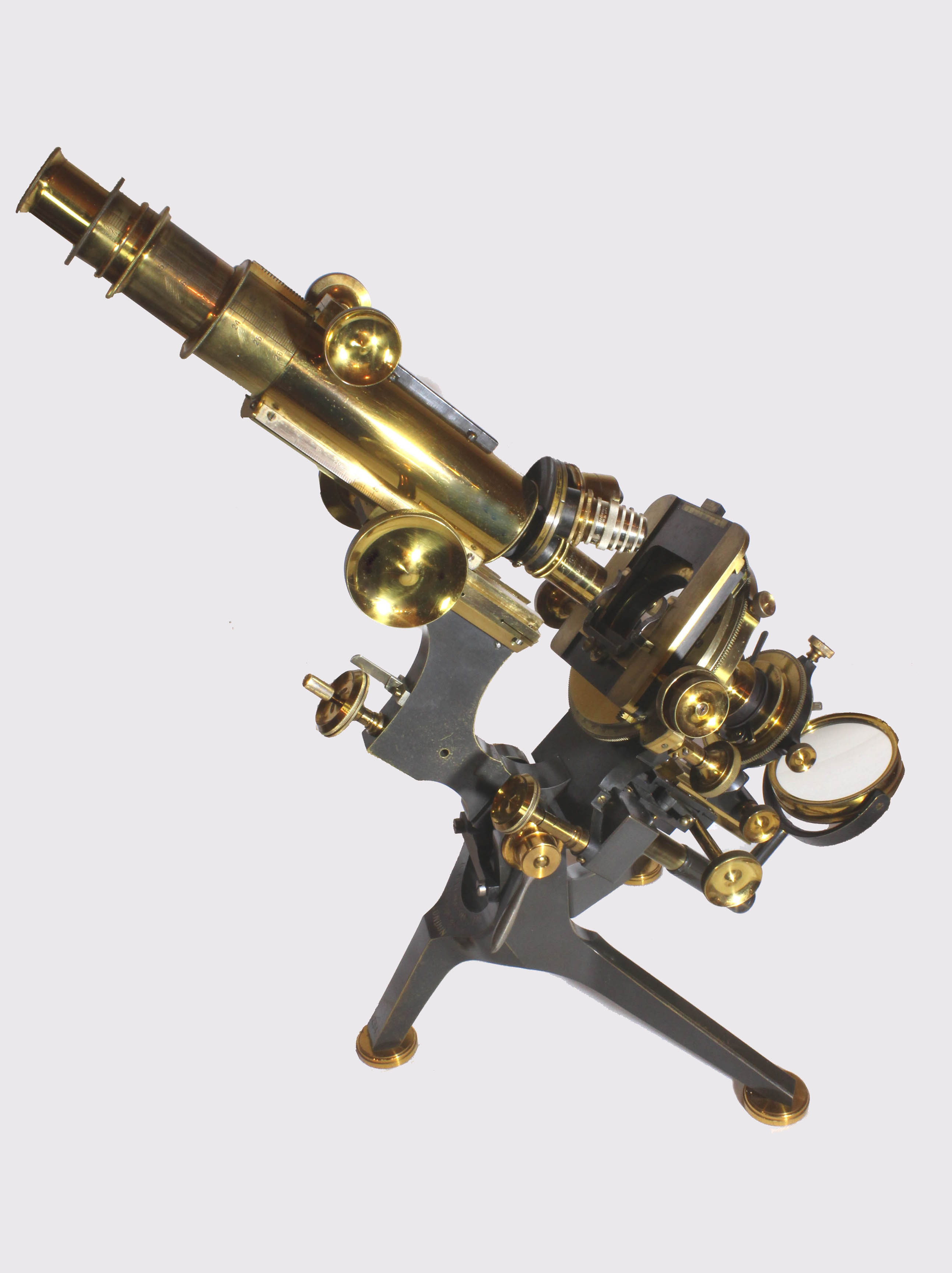
 As noted above, the Van Heurck instrument, as designed by the
diatomist, was at first provided on a continental foot with a single
pillar. Early examples had a standard one inch diameter main optical
tube, as pictured in the image in the preceding paragraph. In the 1893
catalog the 'No. 4 Van Heurck Stand A' had a 1 inch diameter main
optical tube with a single calibrated draw tube with tube length
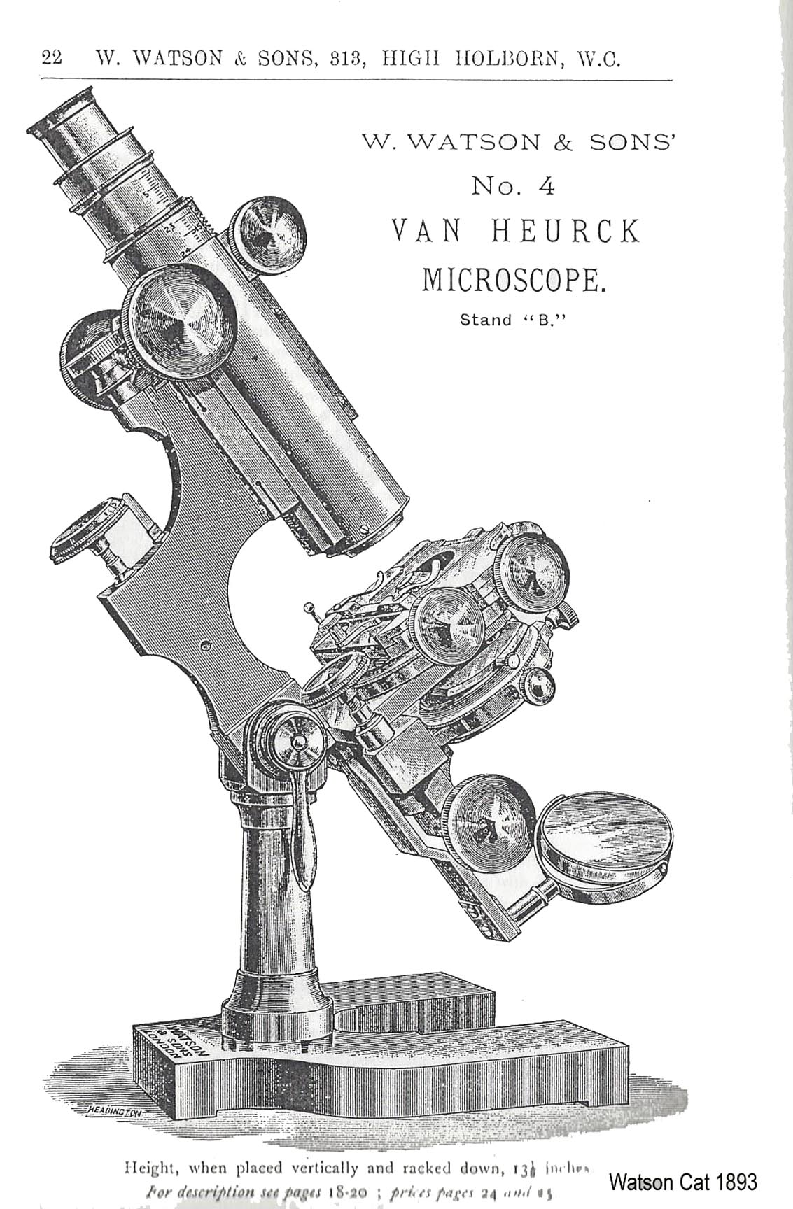
variable from about 160 mm to 260 mm. The 'No. 4 Van Heurck Stand B,'
as shown to the left, had a double drawtube, the lower draw wider, (but
still only 1.5 inches in diameter), and controlled by rack and pinion.
In the 'B' stand the combined tube length could be varied from about
142 to 305 mm. It could be ordered as pictured with a continental foot,
or for a slightly higher price with a tripod foot. The Van Heurck was
apparently not yet considered the 'top of the line' instrument as No. 1
was the impressive 'Watson Swinging Substage Microscope,' No. 2 was the
'Scientist's,' and No 3. was the 'Research.'
As noted above, the Van Heurck instrument, as designed by the
diatomist, was at first provided on a continental foot with a single
pillar. Early examples had a standard one inch diameter main optical
tube, as pictured in the image in the preceding paragraph. In the 1893
catalog the 'No. 4 Van Heurck Stand A' had a 1 inch diameter main
optical tube with a single calibrated draw tube with tube length
variable from about 160 mm to 260 mm. The 'No. 4 Van Heurck Stand B,'
as shown to the left, had a double drawtube, the lower draw wider, (but
still only 1.5 inches in diameter), and controlled by rack and pinion.
In the 'B' stand the combined tube length could be varied from about
142 to 305 mm. It could be ordered as pictured with a continental foot,
or for a slightly higher price with a tripod foot. The Van Heurck was
apparently not yet considered the 'top of the line' instrument as No. 1
was the impressive 'Watson Swinging Substage Microscope,' No. 2 was the
'Scientist's,' and No 3. was the 'Research.' 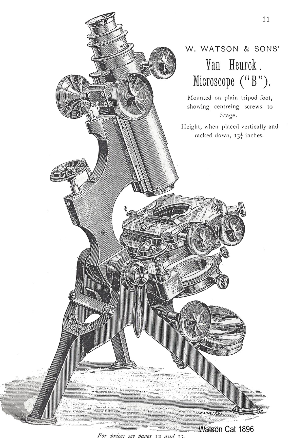
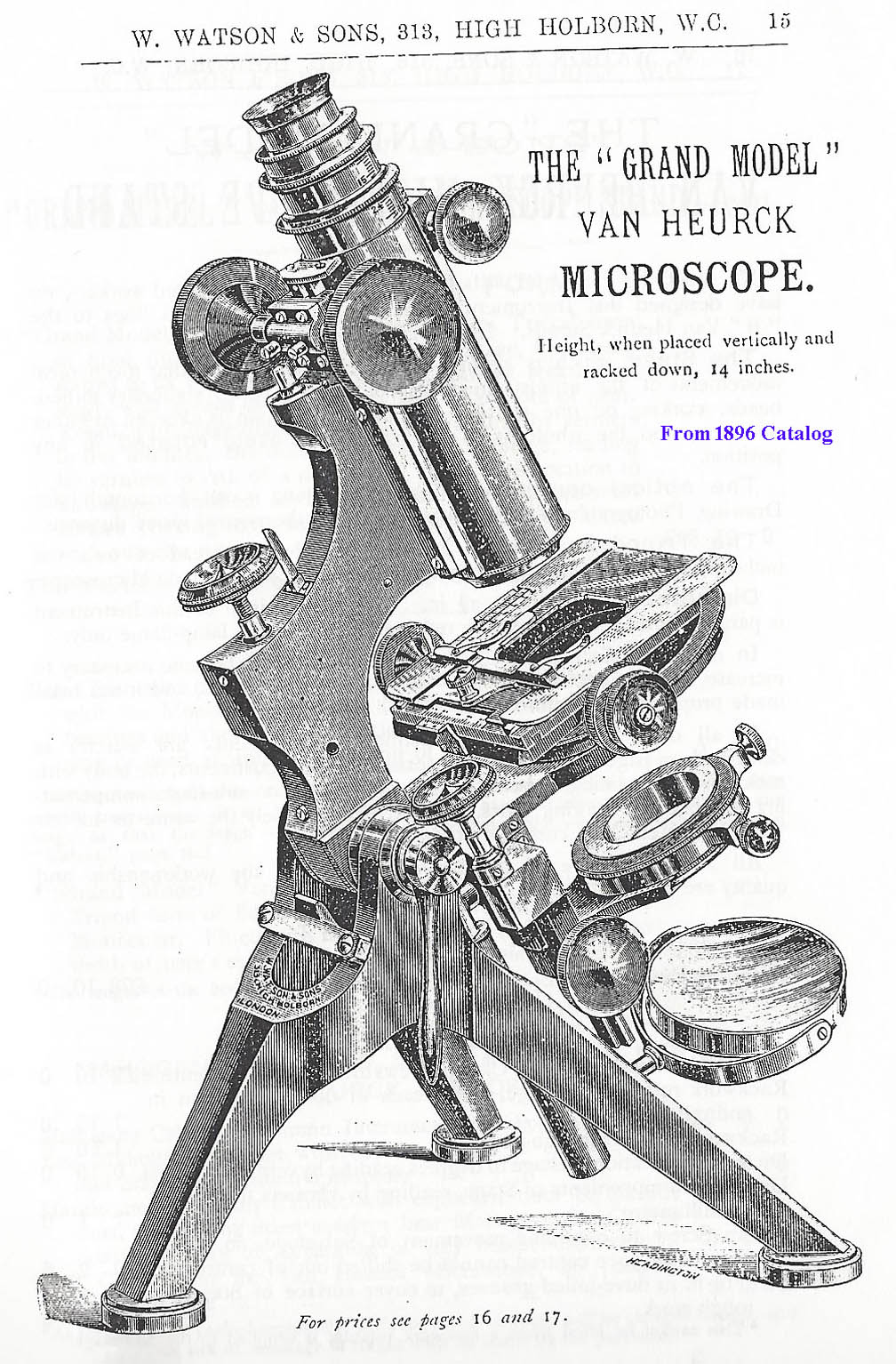 In 1896, stand 'A' was no longer listed, but the usual Van Heurck was
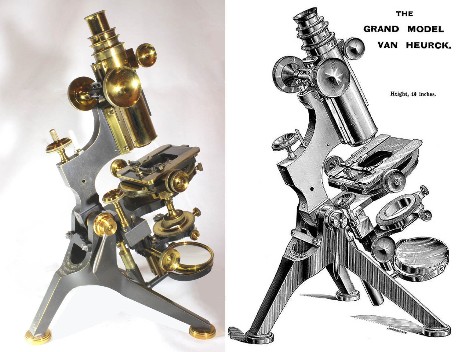
still called the 'B', available with a continental or, as seen to the left, a tripod foot Also in 1896, the 'Grand Model Van Heurck Microscope Stand' (right) was first listed in the catalog. At that time it was listed as identical to the B stand except for three new features: 1)concentric controls for the mechanical stage (after Terrell), 2)complete rotation of the stage, and 3)a slightly larger foot with the Grand, the spread of the foot 'more than ten inches'.
In 1896, stand 'A' was no longer listed, but the usual Van Heurck was
still called the 'B', available with a continental or, as seen to the left, a tripod foot Also in 1896, the 'Grand Model Van Heurck Microscope Stand' (right) was first listed in the catalog. At that time it was listed as identical to the B stand except for three new features: 1)concentric controls for the mechanical stage (after Terrell), 2)complete rotation of the stage, and 3)a slightly larger foot with the Grand, the spread of the foot 'more than ten inches'. 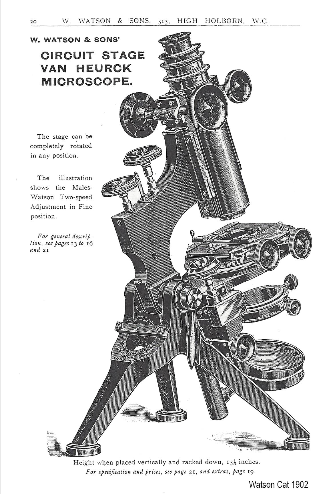 The
'Circuit Stage Van Heurck' was apparently first introduced about 1899
(as quoted in the Illustrated Annual of Microscopy for 1900). Like the
Grand Model, it had complete rotation to the stage, but was otherwise
identical to the smaller Van Heurck (now just called the Van Heurck
without a letter or number), including the stage controls. Later on,
the basic model simply became the 'No 1 Van Heurck'.
The
'Circuit Stage Van Heurck' was apparently first introduced about 1899
(as quoted in the Illustrated Annual of Microscopy for 1900). Like the
Grand Model, it had complete rotation to the stage, but was otherwise
identical to the smaller Van Heurck (now just called the Van Heurck
without a letter or number), including the stage controls. Later on,
the basic model simply became the 'No 1 Van Heurck'. | VAN HEURCK NO. 4, 'A' MODEL | ||
| DATES | STANDARD FEATURES |
OPTIONAL FEATURES |
|---|---|---|
| 1893 | Horseshoe foot, single draw, Mechanical Stage with separate controls for horizontal and vertical motion which rotates but not a full 360 degrees, Substage Fine Adjustment, Projecting upwards in back of stage, clamping lever for inclination Joint. The mechanical draw-tube length can vary from 160 to 260 mm. |
Tripod foot, Binocular Body,
Centering Screws
to stage with clamping, Rackwork rotation to stage, Divisions to stage,
Divisions to Horizontal and Vertical movements of stage, Rackwork
rotation to sub-stage, Clamping of
substage centering, |
| 1896 | The 'A' Stand is no longer offered in the catalog | |
| VAN HEURCK NO. 4, 'B' MODEL | ||
| DATES | STANDARD FEATURES |
OPTIONAL FEATURES |
| 1893 | Double Draw, with one Mechanical Draw tube, otherwise same as 'A' but with the extra draw-tube , the mechanical tube length has a longer range of from 142 to 310 mm. | Tripod Foot, Binocular Body |
| 1896 | Tripod Foot now standard, otherwise same as 1893 | same as 1893, except now the Horseshoe foot was optional |
| VAN HEURCK NO. 1 | ||
| DATES | STANDARD FEATURES |
OPTIONAL FEATURES |
| 1900 | Same as Van Heurck B of 1896 | Same as 1896 with additional option of Strnger's fine adjustment |
| 1902 | same | Same but also the Males-Watson fine adjustment and the Spindle head fine adjustment AND hinged substage which can be turned aside out of the optical axis |
| 1906 | same | same |
| 1912 | same except now the substage fine adjustment is an option | Choice of above or below stage substage fine adjustment |
| 1918 | same except now all Van Heurcks have hinged substage standard, which allows the substage to be turned aside and out of the optical axis | same as 1912 |
| 1921 | same as 1912, but now the substage bar extension sliding on dovetail to allow greater range of accessories of different heights as was previously only offered for the Grand, then the Circuit stage, is now offered for all Van Heurcks | |
| 1923 | ||
| VAN HEURCK CIRCUIT STAGE MODEL | ||
| DATES | STANDARD FEATURES |
OPTIONAL FEATURES |
| 1900 | Identical to No. 1 but with complete stage rotation | Identical to No. 1 |
| 1906 | Same as 1900 | Same as 1900 |
| 1912 | same except now the substage fine adjustment is an option | Choice of above or below stage control of substage fine adjustment |
| 1918 | same except now all Van Heurcks have hinged substage standard, which allows the substage to be turned aside and out of the optical axis | same as 1912, but now the substage bar extension sliding on dovetail to allow greater range of accessories of different heights as was previously only offered for the Grand |
| 1921 | same as 1918 | same as 1918 |
| 1923 | ---- | ---- |
| VAN HEURCK GRAND MODEL | ||
| DATES | STANDARD FEATURES |
OPTIONAL FEATURES |
| 1896 | Identical to the Van Heurck 'B' Stand, with the addition of concentric controls for the mechanical stage, and extension of the stage and arm forward to allow complete stage rotation and larger overall size. | Identical to Van Heurck 'B' model. |
| 1900 | Identical to Circuit stage Model, but larger | Identical to Circuit stage model but optionally the same stage as the No. 1 instead of fully rotating, reduced the price by 3 pounds. |
| 1902 | Identical to Circuit stage Model, but larger | Identical to Circuit stage model
but optionally the
same stage as the No. 1 instead of concentric controls, reduced the
price by 3 pounds. Also option of Stringer's fine
adjustment, or
Males-Watson Two speed fine adjustment, or Spindle Milled-head fine
adjustment, all at extra cost. Optional hinged substage so it can be swung out of the optical axis. Also a substage bar extension sliding on dovetail to allow greater range of accessories of different heights. |
| 1906 | Identical to 1902 | Same as 1902 but also offered the Scop Mechanical Stage instead of the usual circuit stage, price the same as the standard model. |
| 1912 | same | same as 1906 |
| 1918 | same except now all Van Heurcks have hinged substage standard, which allows the substage to be turned aside and out of the optical axis | |
| 1921 | Same | Side Limb or Horizontal fine adjustment for same price. |