aberration, and leads to a deterioration in the quality of the image, and hence, resolution. It is important to note, that this
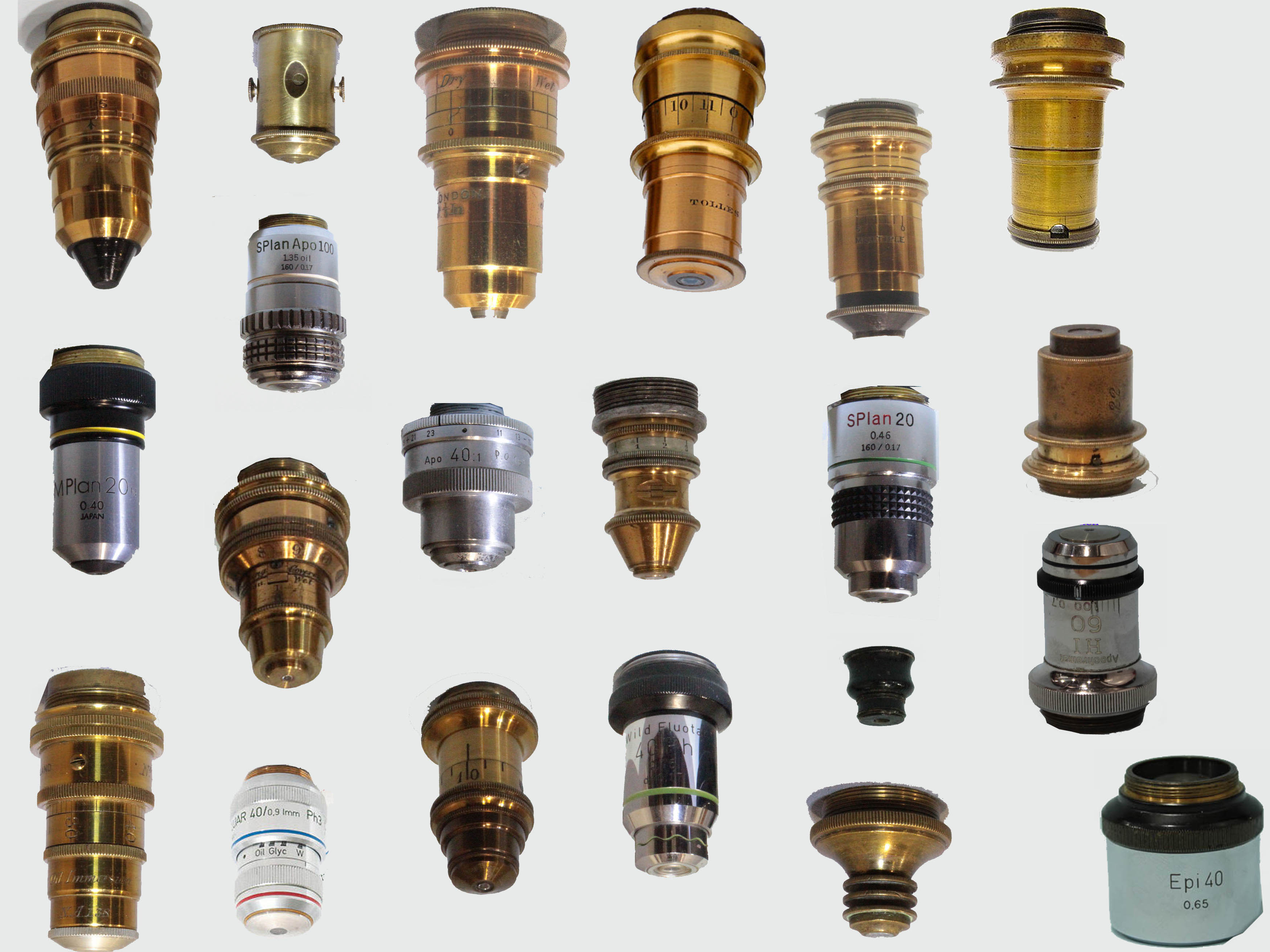
perfect objectivehas never been achieved, although modern plan-apochromats come very close. Before this paradigm shift, simple microscopes using single lenses of various types showed less distorted images than compound instruments at the same magnification, because the multiple lenses in compound microscopes multiplied the aberrations. This web page is an attempt to illustrate the various types of microscope objectives found with compound microscopes and review their evolution over time. We start our discussion in the 1700s, the period from which time onward, a number of examples are still extant.

2on the threaded end, indicating that it was the second to highest power of a set for the microscope it was made for. When viewed under a stereo microscope, this lens has some scratches and scuffs on both surfaces. This pre-achromatic objective produces fair images, but with expected chromatic and spherical aberration.
the trade, and were ground by hand by people, sometimes children, working from home, so tolerances could be wide, and the surface often fraught by imperfections. Worse still, as the lens was loose (some rattle when handled), centering was poor, which all led to an increase in aberrations. These were not well understood, and many observers, using these objectives, believed they saw actual structures that were, in actuality, nothing more than severe distortions that did not represent the actual structures observed. Because of the high magnification, uncorrected for aberrations, many objects appeared to be nothing but vague round blobs. Some observers, such as Milne-Edwards went so far as to believe that all objects were composed of "globules". Today we refer to magnifications which show no more fine detail as empty magnification.
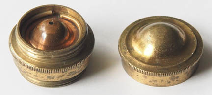
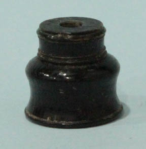
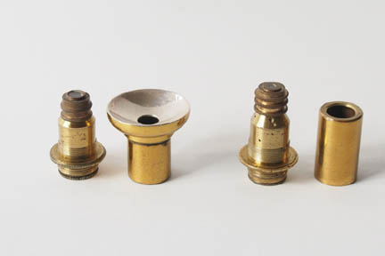
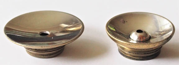 For the observation of opaque objects, pre-achromatic objectives were constructed featuring a silver mirror in which a central aperture, behind which the chromatic lens was mounted. In these, access to the lens itself is gained by unscrewing a small ring at the rear of the assembly. This type of objective was originally popularized by Johannes Nathaniel Lieberkuhn (1711-1756), a physician, who used this design first on a simple microscope incorporating a small silver speculum, which had to be of a similar focal length as the objective lens, in order to reflect the maximum amount of light on the specimen when in focus. The image to the left shows 2 Lieberkuhn objectives of different focal lengths from the set as also shown belonging to a George Adams microscope Ca 1790.
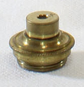
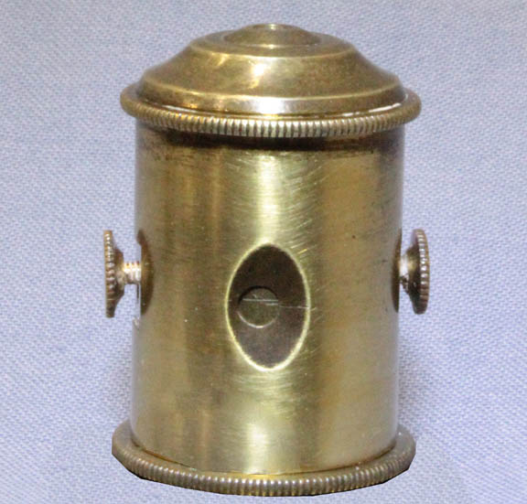
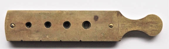 A completely different method of mounting multiple objective lenses was first used on solar and simple microscopes, but soon also in compound instruments. These "objective sliders" often featured 4 or 6 biconvex lenses clamped between two longitudinal brass plates, sliding in a dovetailed ring which was affixed to the arm of the microscope. A sprung pawl acted on notched recesses, to ensure that once chosen, each lens would be centered at the end of the optical tube. One such slider from a chest microscope retailed by Schmalcalder is shown to the left.
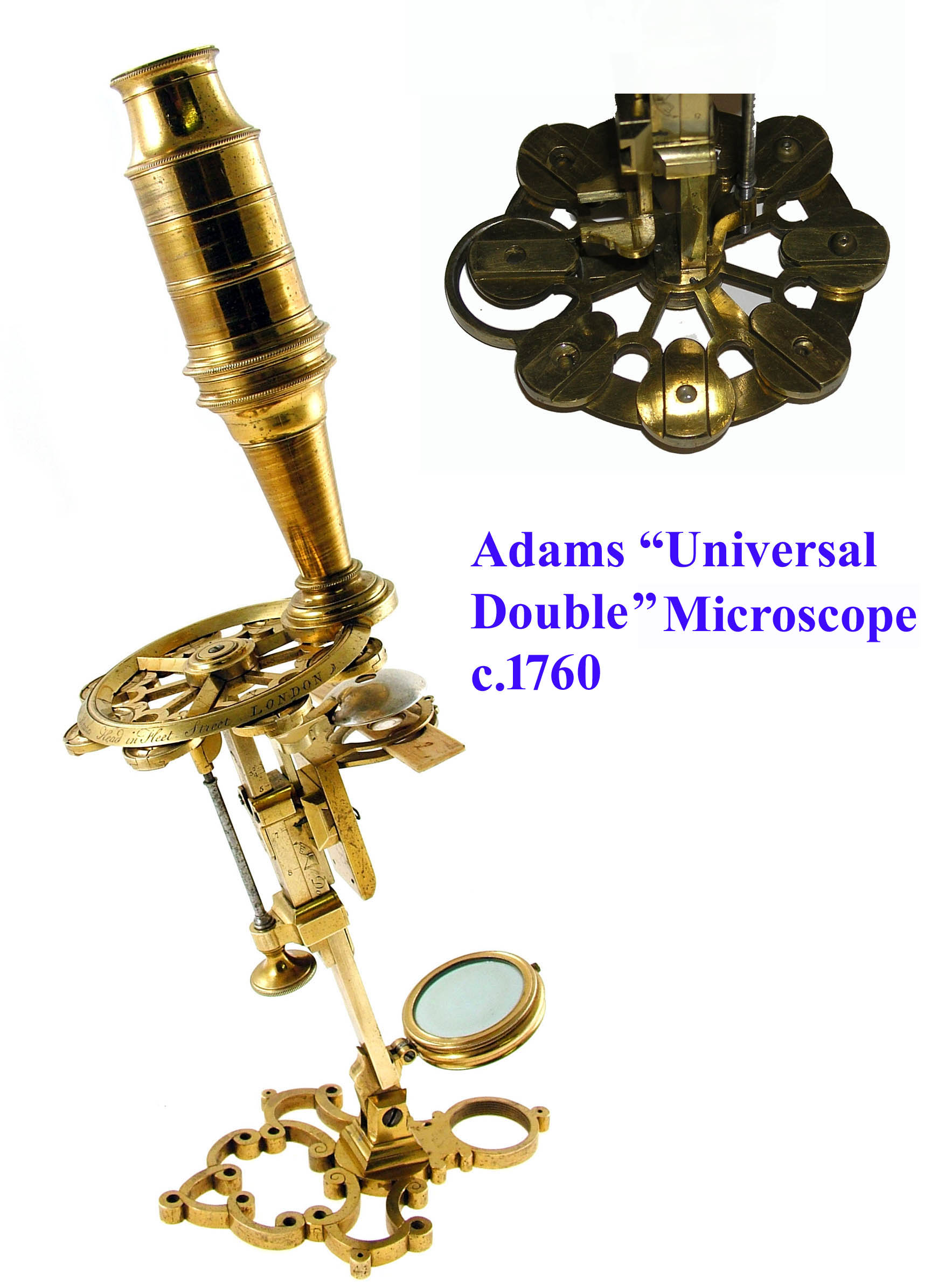
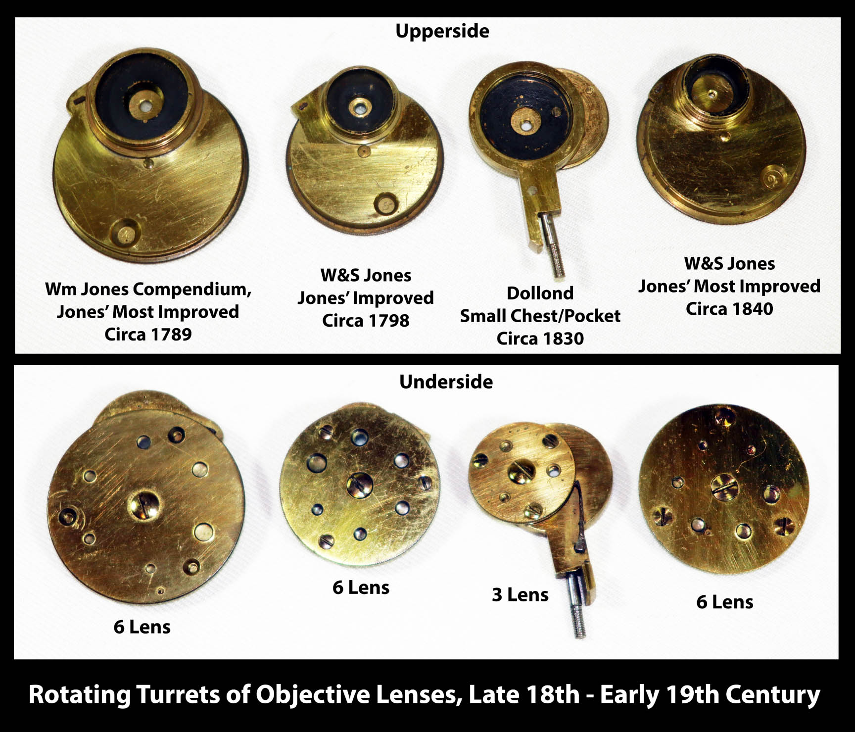 This era also saw the first use of a rotating nosepiece, in which a number of biconvex lenses were held between two circular brass plates instead of a slider. This feature first appeared on Adams's "New Universal double microscope" (left), but W. and S. Jones and then others, later employed a much more compact version on their "Most Improved" model, as seen in the examples shown to the right. Later on, as objectives became more complicated, heavier, and longer, nosepieces were made to accomodate objectives of the user's choosing, intiially as a nosepiece double objective changer, and later, in the 20th century, accomodating up to six objectives in a shallow cone-shaped device.
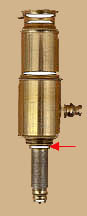
between-lensplaced at the top of the snout carrying the single lens objective, whereby this lens, which was often 4 or 5 inches in focus, functioned as the back lens for the whole series of objectives. This reduced the working distance of the objective, and effectively brought a slight improvement in its angle of aperture.
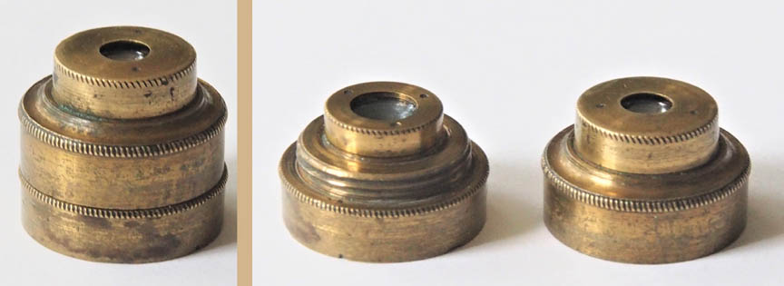
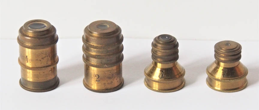
 Anticipating the later use of "achromatic buttons", some makers resorted to the use of stacked biconvex non-achromatic lenses contained in brass cells, which screwed onto each other. This divided the amount of spherical aberration of one lens over several lenses with bigger radii, while also providing a selection of magnifications with the use of different lens combinations. The objective shown on the left is from a Dutch chest microscope C.1780, and has a front lens marked '2' and back lens marked '3' in engraved dots. The other objective, shown to the right, features 3 non-achromatic buttons, each holding a biconcave lens of the same focal length, belongs to a chest microscope retailed by Mathew Berge,successor to Jesse Ramsden,and can be dated 1800-1819. Astonishingly, objectives made up of multiple small non-achromatic lenses separated by little fiber rings continue to be made today, and can be found in cheap toy microscopes, often sold as kits for children. Inevitably, these produce much empty magnification, which does little to promote microscopy as a hobby.
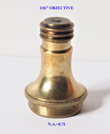
 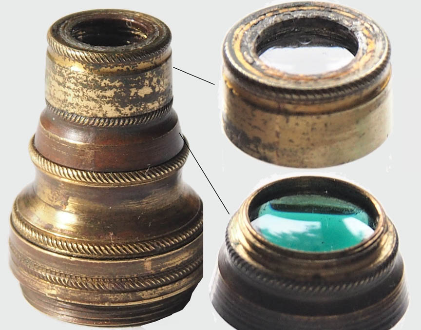 It is not well known that even before the advent of achromatics, there was a period of experimentation aimed at improving the resolution of the pre-achromatic objective. To date, the authors have not been able to find a reference to the mystery objective shown on the left, which is made up out of 2 positive meniscus lenses*, the front element being of clear- and the back lens being made of blue-green glass. The concave surfaces are turned towards the object, which hints at an attempt to correct spherical aberration, while the colored glass may have been aimed at making it monochromatic, and hence less suceptible to chromatic aberration. Focal length is about 5 mm, and, being not stopped down, its N.A. is about 0.25. Only part of this aperture can be utilized, as the maximum resolution of about 2 um can only be achieved with a narrow cone of light. The outer diameter of the threads of this objective is 15.5 mm and the thread pitch is 36 t.p.i.
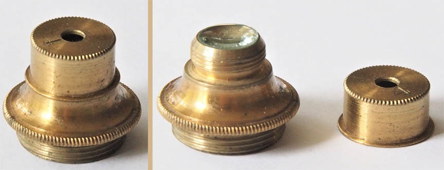
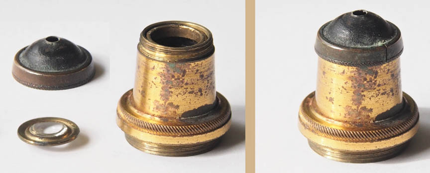 The objective shown here achieves a similar performance via simpler means, and consists of a plano-convex lens contained in a flat brass ring, which is held in place by a screw-on external stop, which is placed before the rear lens, which has its flat surface towards the object. Again, the working distance is short, but due to the placement of the stop more light rays from the object can be utilized, than would have been the case, if such a small aperture had been located immediately behind the lens. Resolution, as measured using a Graticules 50x2 um slide, is also 2 um. It has the same thread diameter and pitch as the prior entry.
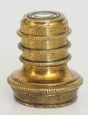
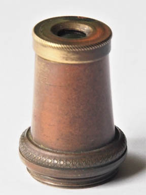 The third objective, which came with the 2 pictured in the previous 2 paragraphs, features a low-power plano-convex lens, but is different in shape than most objectives from the pre-achromatic era. All 3 objectives shown here carry the same 15.5 mm diameter thread, and it is tempting to speculate, that they were once used on the same microscope. The big question remains, as to whether they pre-date the appearance of the first achromatic doublet objectives, or were made around the same time by someone seeking to replicate their improved resolution via other means? This objective has the same thread diameter and pitch as the prior two entries.
 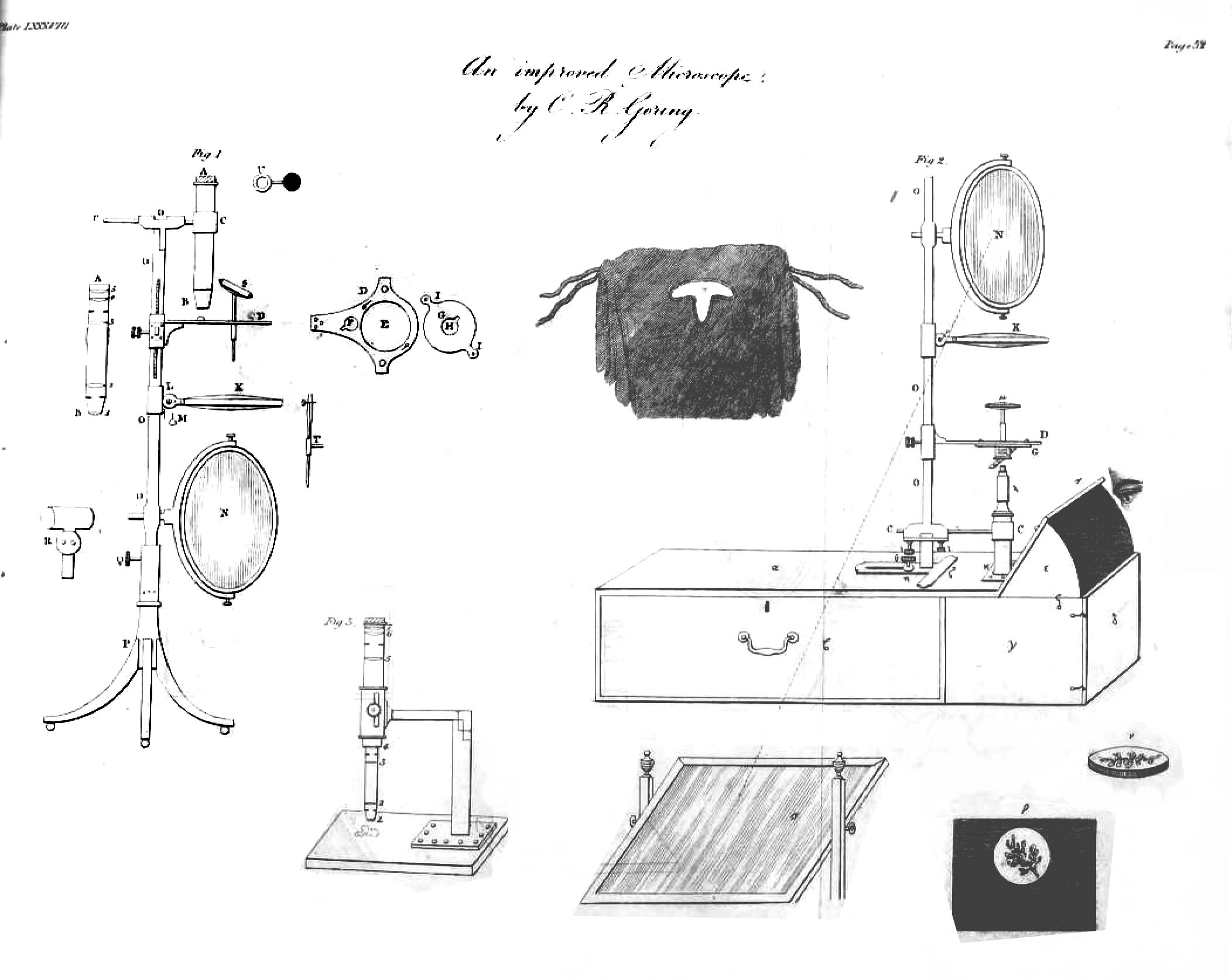 In 1819 Goring published his own paper Description of an improved Microscope (Thomson Annal of Philosophy; Vol. 13, pp. 52-59), describing his version of a microscope(left), which can be used for the examination of opaque, and transparent objects, and which, in inverted form, can be used as a solar microscope, projecting its image inside a box acting as a camera obscura. Its objective consists of two biconvex lenses, mounted at a certain distance, having an aperture stop in between. It is explained that the latter configuration is similar to those used for the eye-pieces of refracting telescopes (the image inverting part). In this earlier version, three different astronomic eye-pieces are used to increase the magnification. Goring states, that
 this instrument was made by that acute and distinguished artist, Mr. Adie, of Edinburgh,.., and features a large oval mirror, as well as an under stage condensing lens. The objective is obviously stopped down to a lesser extent, than was usual at the time, as Goring asserts that it provides
an abundance of lightwhen viewing opaque objects.
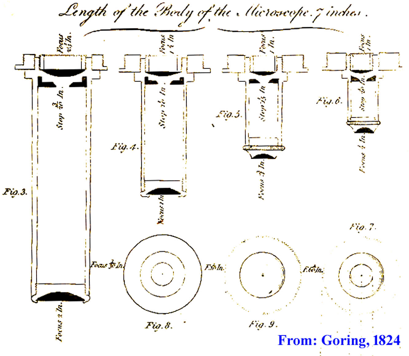 It appears that Goring continued to experiment with chromatic objectives over successive years, as in 1824 he publishes another paper (Quart. J. of Science, Litt. and the arts, Vol. 17 pp. 202-209) where he describes a set of improved microscope objectives(right) with focal lengths ranging from 2 to 1/2 inch, which consist of 2 plano-convex lenses, with their convex surfaces turned inwards, and whereby a stop is placed in the focal plane of the front lens, i.e.
 where the rays cross each other. The back lens (with a focal length between 3 to 2 up to 2 to 1 times the focal length of the front lens) is placed closely above the stop. Goring claims that:
these object-glasses I can confidently recommend as greatly superior to those in common use; they are bright, clear, and distinct, free from spherical aberration, and will shew no sensible colour with opaque objects of any kind.., but:
When, however, they are made to view an object illuminated from behind, which does not suffer the light to pass through it while its edges are seen, as for example the legs of some insects, some kinds of moss, &c, which have little transparency, the uncorrected colour is then decidedly seen.Goring reports, that this type of objective only works well up to focal lengths of up to 1/4 inch, and had a number of
silver cupsmade
for holding very deep single lenses (of shorter focal length) intended to view opaque objects, which, together with the object-glasses before-mentioned, were executed for me by Mr. Tuther, optician, in High Holborn..(see illustration, right). By now, Goring had obviosly moved back to London, as he also states that:
Mr. Varley and Mr. William Tulley, of Islington, are the only individuals who can make such deep lenses as they ought to be made. Around this time, he also meets Andrew Pritchard, with whom, for awhile, he worked on developing Jewel lenses to be used as simple microscopes, before -in 1825- commissioning William Tulley to make him
a triple achromatic lens of 0.33 inch focus, which heralds the true beginning of the achromatic period. Goring's non-achromatic object glass for low powers is mentioned as late as 1837 in Sir David Brewster's Treatise on the Microscope, with the addition:
Mr Pritchard remarks, that when the focal length of the lens A (front lens) is not less than half an inch, this combination has been employed with considerable advantage, both as regards distinctness and aperture.
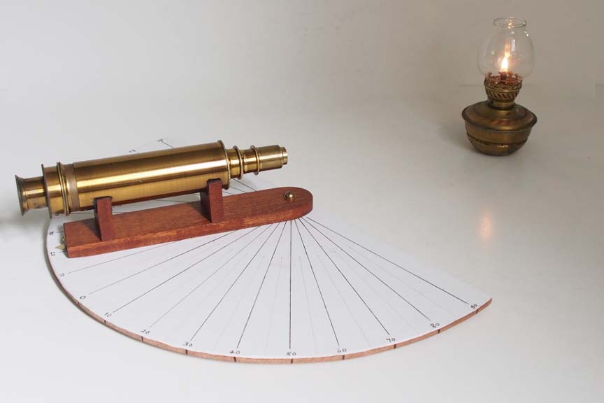
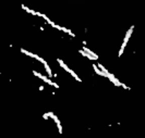
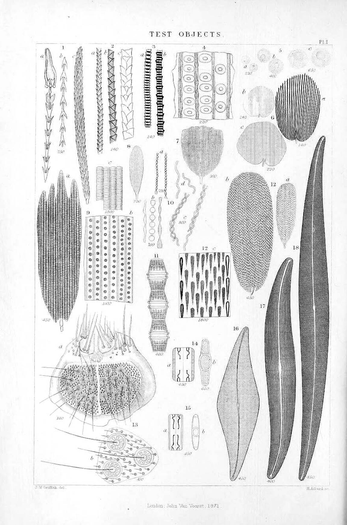 Spherical aberration occurs, when light rays which pass through the periphery (thinner part) don't focus in the same point as those which pass through the center (thicker part) of a lens, this, regardless of the colour of the light, so achromatic combinations also suffer from this problem. In a single achromatic combination consisting of a crown- and flint glass lens bonded together, spherical aberration can be reduced by stopping the aperture down, thereby excluding the peripheral rays from distorting the image, but this reduces resolution. Worse still, when more lenses are combined, they magnify each other's spherical aberration, so further stopping down would be required. From around 1825 it was realized, that a more scientific approach was required to measure the performance of microscope objectives, in order to be able to test the correction of spherical aberration in different lens combinations. The credit for coming up with the idea of test objects, so that the resolution of different objectives could be compared, belongs to Dr C.R. Goring. Examples of test objects (from The Micrographic Dictionary), are shown in the illustration to the left and include various objects with regular degrees of separation such as hairs, butterfly wing scales, and diatoms.
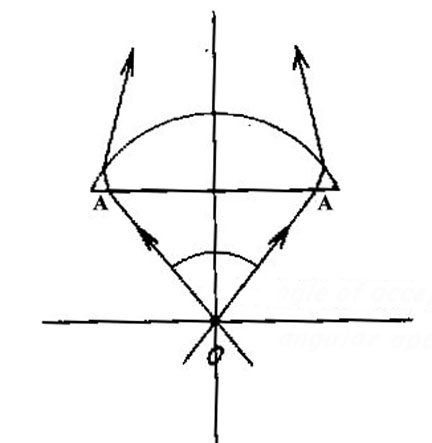
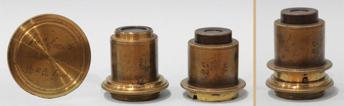
Smith's Quarters. Later J.B. Dancer followed suit and also supplied this type of objective. The number 22 on this objective refers, unusually, to the serial number of the microscope to which this objective belongs.
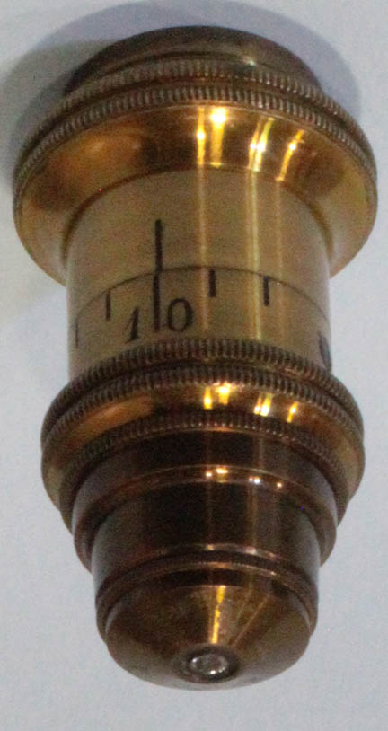
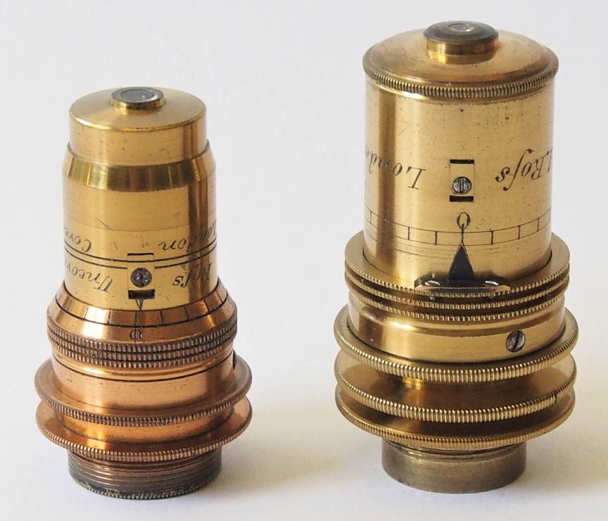 This Ross objective with correction collar has a separate, attached pointer to register the reading of correction on the collar's engraved indication marks. This is a rare form, as this was soon simply done with an engraved arrow on the collar and the numbers engraved on the fixed part of the objective.
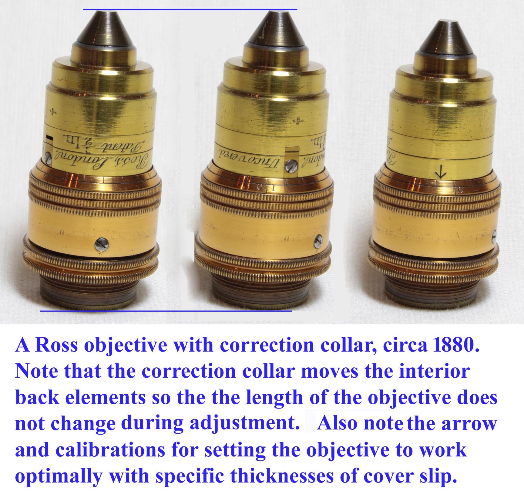
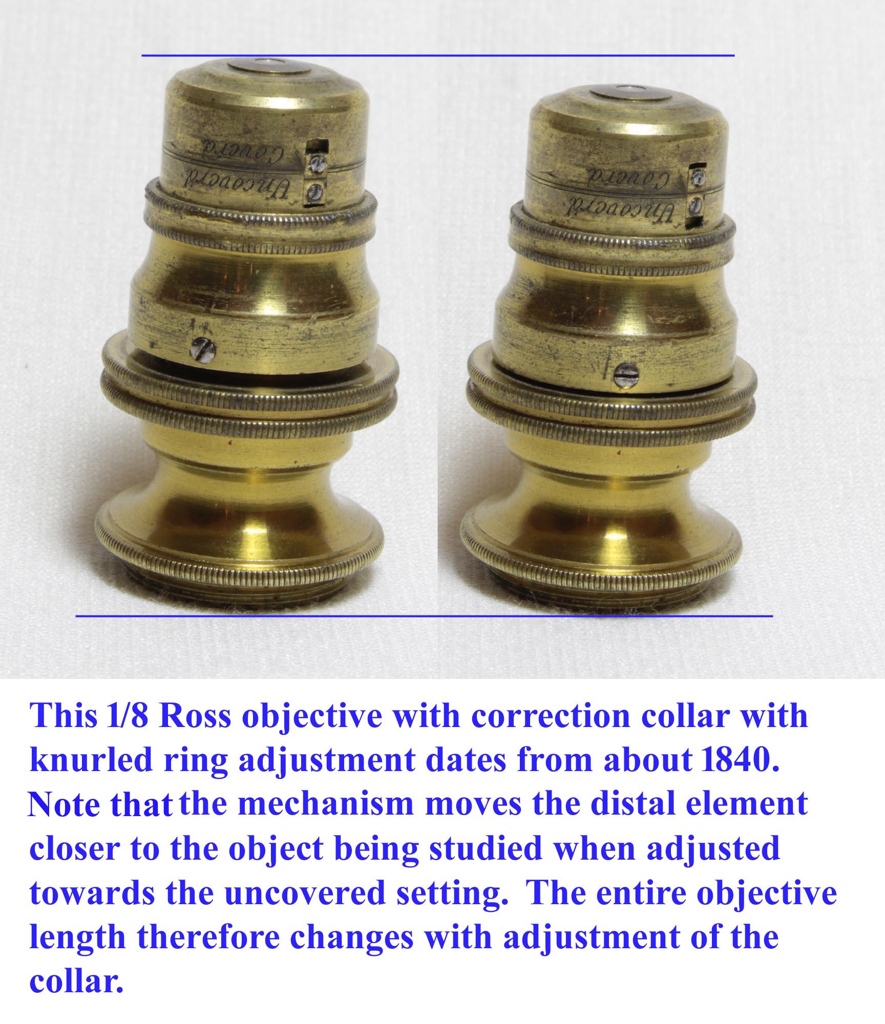
Uncoveredand
Coveredshown on the objective, which is rather inprecise. Many users often employed the
trial and errormethod, whereby with one hand on the correction collar, and the other on the fine adjustment control, the best setting was found which showed the best definition of a given object. Another method, advocated by Andrew Ross, and endorsed by Hugh Powell (in Description of the newly constructed achromatic microscope, 1842), was:
While this method works well for objectives with a longer working distance such as a 1/4 inch, in practice, those with a shorter focal length can not be focused on the object while in the uncovered position,as coverglass thickness prevents this, and the opposite procedure is required: set the correction on fully covered, focus on the top of the coverslip, and then turn the correction collar down, i.e. a bit more towards the uncovered position in order to bring the object into focus. One finds that with objectives of a very short focal length and working distance, the object can still not be brought into focus even with the correction collar in the maximum covered position. These objectives were made to be used with extra thin cover glasses, such as those which Powell & Lealand commissioned from Messrs Chance, which reportedly were only 0.05 mm thick.To place it at the point for viewing objects uncovered, which will be known by observing that the circular line under the word uncovered corresponds with the fixed line; or:, the more ready way is, to adjust it down as far as it will allow, as we always make them to stop at the corrected point. Bring the object into focus by adjustment of the body, then adjust the object-glass till the upper surface of the glass which covers the object is in focus; this can very readily be done while the person is observing, by taking between finger and thumb the milling on the object-glass, and turning it to the left; then bring the object again into focus by the body, and the adjustment is perfect
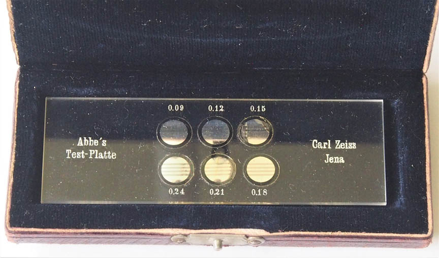
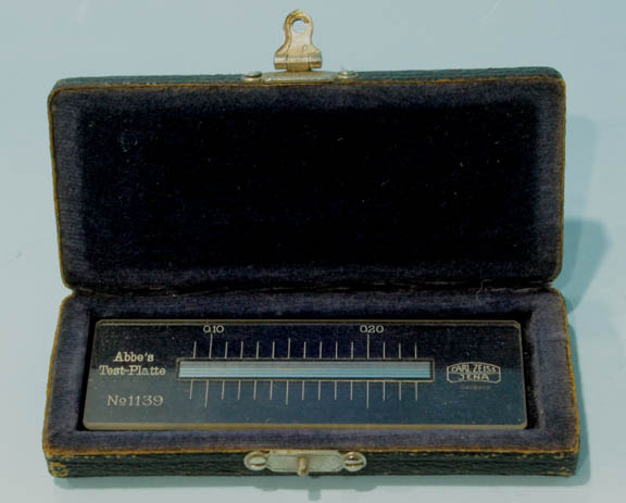 Over time, more scientific methods were developed to define the point of optimum correction for these objectives. Abbe introduced the test plate(left) for checking spherical correction. It consisted of a set of six small cover slips of different measured thicknesses mounted side by side on a microscope slide and having their under surfaces silvered and ruled to produce parallel bright and dark bars. The microscope was brought into focus on the bars under one cover in a narrow cone of axial light, and the illumination was then made oblique by racking the closed iris diaphragm to the margin of the condenser aperture (a feature on Zeiss microscopes). If the focal level of the image remained constant, this demonstrated that the full aperture of the objective was working uniformly; if the marginal focus differed from the axial focus, the full lens aperture was not being constructively used towards creating the image. The thicker covers introduced an error in one direction, the thinner ones in the opposite, and by adjusting the correction collar (or the tube length), an objective could be matched to any of them. The later version of the test plate used a single long coverslip, tapering in thickness from end to end, with the thickness engraved on the slides at points along the length(right).
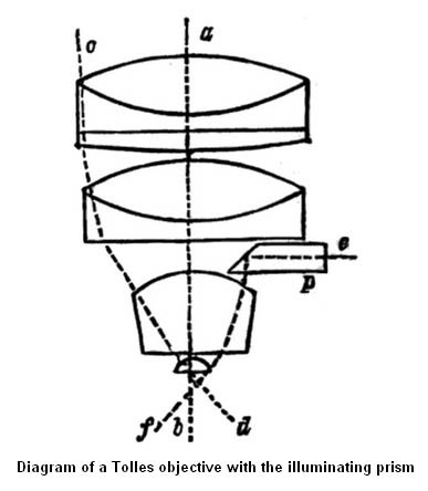
 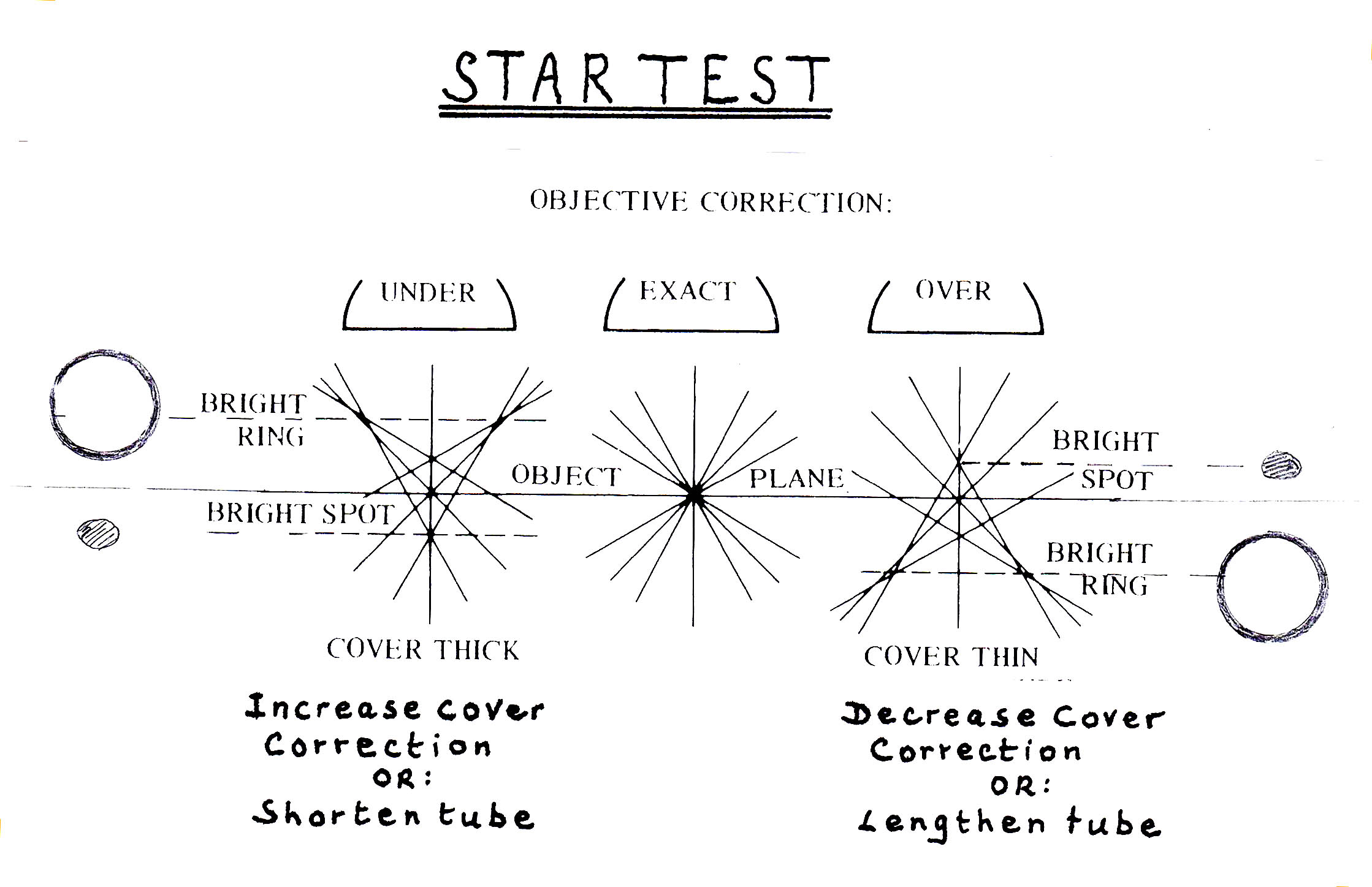 For most purposes, the Abbe test plate has been superceded by the simpler and more sensitive star test. This compares the out-of-focus appearances of a small bright point in the image above and below the level at which the Airy disc has its minimum diameter.These tiny bright spots can be created by examining a cover slip, the under surface of which has been silvered, leaving small perforations. For the testing of immersion objectives, the top of the slide itself is silvered. The star test depends on the fact that if the objective is free from spherical aberration, the distribution of light in the discs seen above and below the point of focus ought to be identical.If the central focus of the objective is shorter than its marginal focus - i.e. if it is over-corrected- the light will form a bright spot below the true focal plane, and a ring above it, owing to the uneven distribution of light rays. The reverse effect occurs with an undercorrected lens. The correction collar is then used to get an as symmetrical effect as possible, i.e. the same appearance above- and below the focal point. As an alternative, adjustments can be made to the length of the draw tube (see diagram). In principle, this test can also be performed when focusing on a small dark speck in the slide to be examined against a bright background, and examining the out of focus images above and below the focal plane, but this requires a bit more practice.
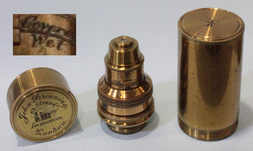
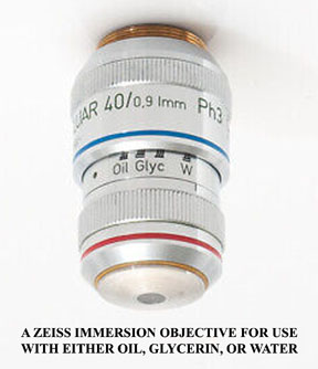
Coveredand for
Wet, the latter indicating water immersion, and the angular aperture of 135o, which corresponds to a numerical aperture of 1.23 when used as an immersion lens in water, or 0.924 in air-its not clear which this was referring to.
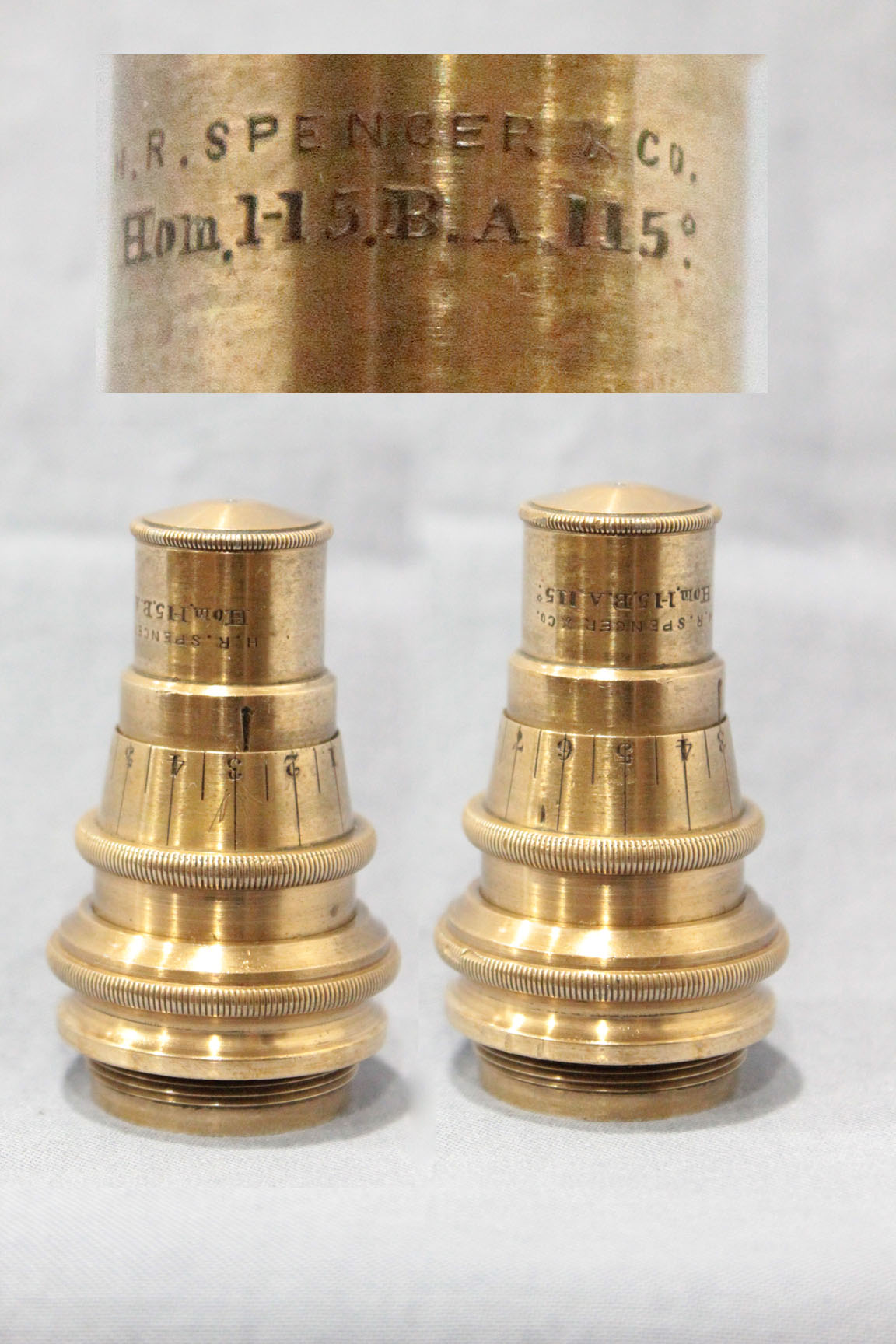
balsam angleor B.A. for the angular aperture of an immersion objective in balsam and this was sometimes inscribed on the objectives of the time, and for some time afterwards, as seen on the Herbert Spencer Objective shown to the left. By 1870, Zeiss, with the help of Abbe, was making all their objectives by calculation; in 1873, the year that Abbe published his scientific work on the resolution of objectives relating to numerical aperture, Tolles made his famous 1/10 inch homogenous immersion objective with a N.A. of 1.25. But Balsam was hard to work with and hardened with time and so was not ideal. Tolles made a glycerine immersion objective that same year. In 1877 Abbe, after testing hundreds of liquids, discovered that Cedarwood oil has a refractive index(1.516) close to glass, and all his oil immersion lenses were then designed to work with this; within a few years Cedarwood Oil replaced softened Canada balsam for all oil immersion objectives.
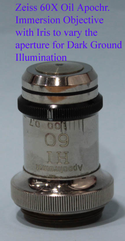
funnel stopfor an ordinary objective, or later,an iris diaphragm built in to the objective. These tiny iris diaphragms are difficult to make and were not common in objectives until the middle of the 20th century.
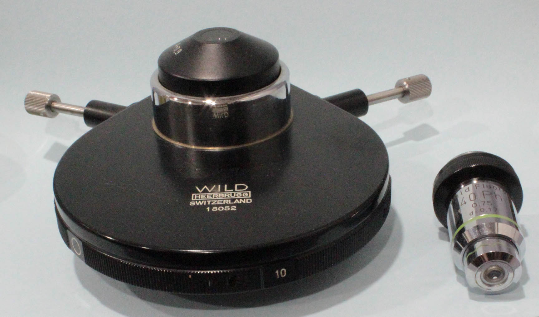
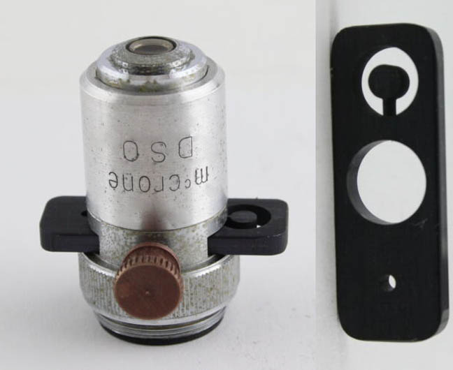
 The 20th century saw a renaissance in new ways to increase contrast. The earliest of these new techniques requiring special objectives was Phase Contrast. So great an achievment was this, that Hans Zernicke, its inventor, was awarded the Nobel Prize in Physics. Zernicke invented the technique in 1932, and it was commercially introduced by Kohler and Loos in 1941. Phase contrast is still used today, in fact one of us (BJS), uses a phase contrast microscope to examine urine specimens almost every day. Phase contrast objectives have a phase ring and require matching phase rings in the condenser. A Wild phase contrast condenser and a 40X Wild Fluotar Phase Contrast objective are shown here to the left. Typically phase contrast objectives are made in 10X, 20X, 40X and 100X(oil) magnifications. An image of a Wild M-20 microscope outifitted for phase contrast is on this site. Wild Fluotar objectives are among the best ever made.
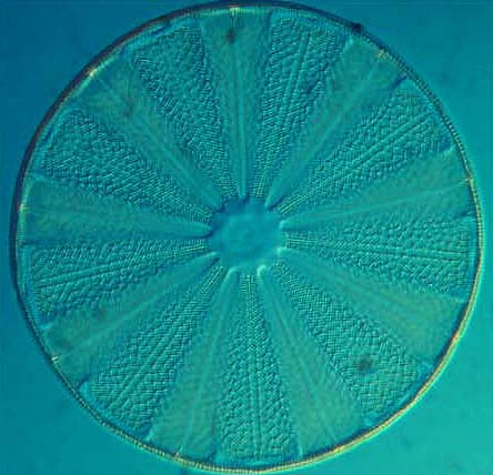
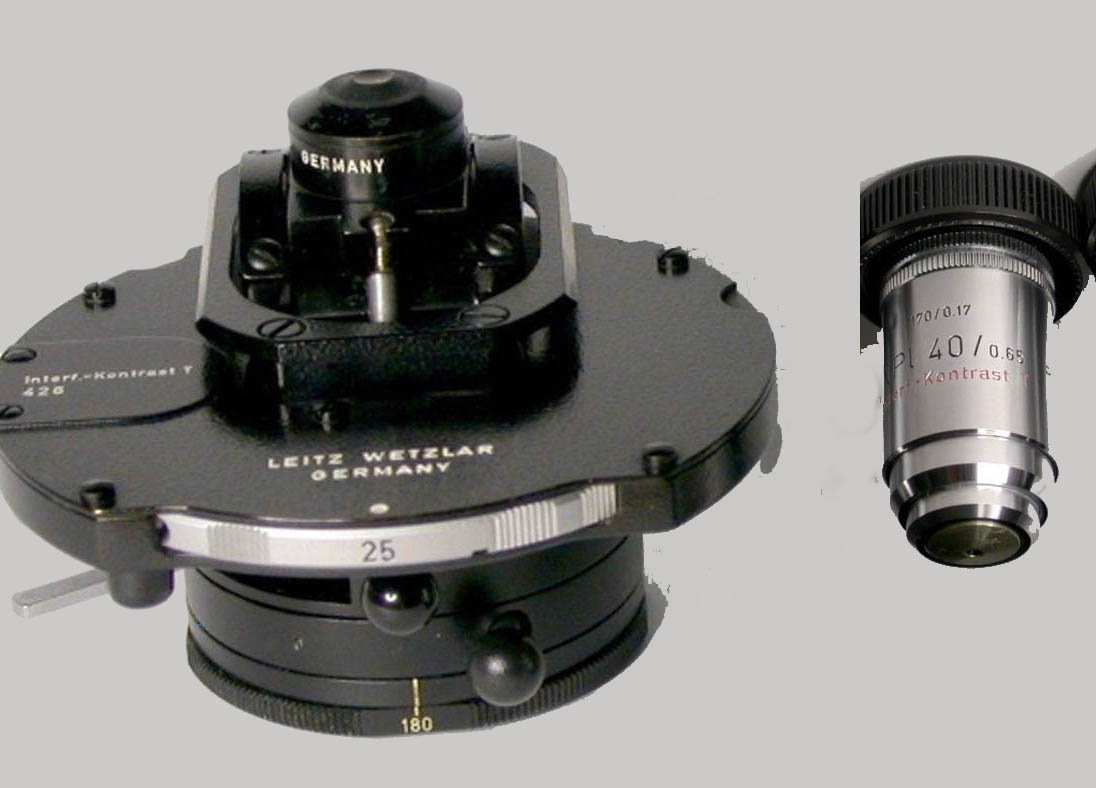
Interference Contrastor, as in the German Leitz objectives seen here,
Interf. Kontrast. There is a manual available for the use of the Leitz apparatus on this site.
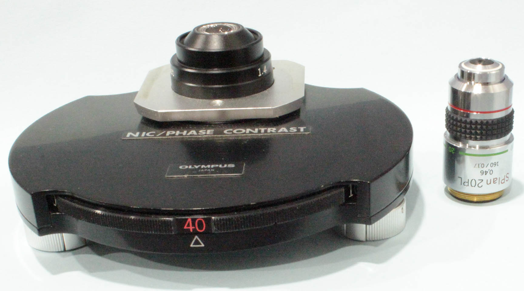
Interference Contrastbecause they have built-in prisms. In addition to strain-free objectives, NIC requires the use of a (NIC) condenser, AND also a NIC intermediate tube containing an adjustable prism, placed between the binocular head and the optical tube. Shown to the left is an olympus combined phase contrast and NIC condenser, along with a typical Olympus 20X S-plan PL objective, that can be used for both phase contrast and DIC work. Note the condenser has an N.A. of 1.4, suitable for high power homogenous oil immersion work. Unlike phase contrast, DIC images have a color imparted to them and also appear three dimensional. The color can be varied by the user to optimize contrast for the particular subject. An Olympus Vanox microscope equipped for NIC as well as phase contrast, is on this site.
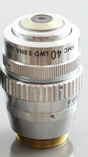
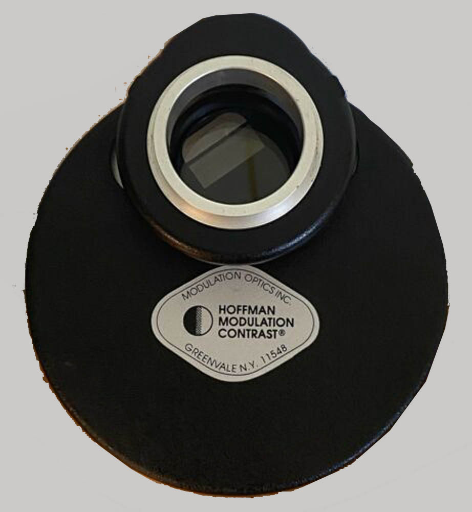
modulatoris placed the rear focal plane of the objectives. Such objectives are labeled with either HMC or the words Hoffman Modulation Contrast spelled out, or simply Modulation.
uncoveredposition, or using objectives designed solely for uncovered use; such objectives became known as
metallographic objectives.
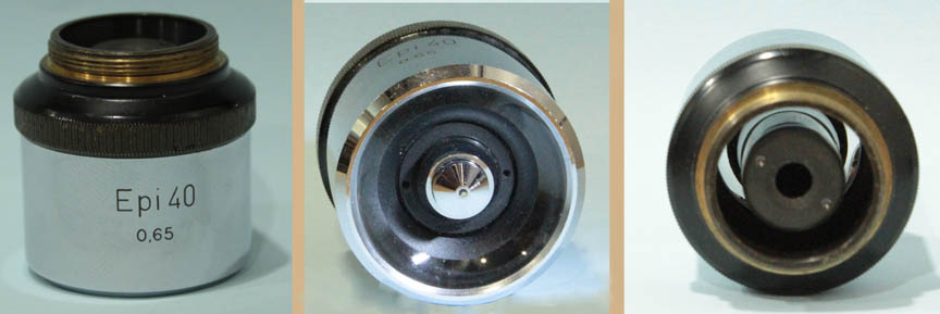
Epi-illumination systems were first developed by Zeiss in the early 20th century. In this type of illumination a directed and focused beam of light surrounds the objective and is arranged such that the optimal plane of illumination conincides with the focusing plane of each objective. These objectives direct highly oblique light on the subject to provide dark ground illumination to opaque objects. These objectives provide a concentric path around the outide of the objective optics that receive the image. An example of a Wild Epi objective is shown here to the left. Note it is much wider than a standard objective because of the accessory light path outside the optics that receive the image.
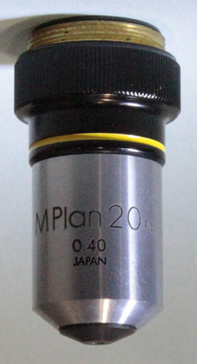
Minscribed on their barrel, as in the M-plan 40X objective by olympus seen to the left. The previously mentioned technique of DIC was also adapted to vertical illumination. A DIC vertical illumination Olympus Vanox microsccope is in this collection and will be featured on this site in the future.
| INSCRIPTION | USUAL MEANING |
|---|---|
| immersion | water immersion |
| wet or dry | dry or water immersion |
| oil | oil immersion |
| gl gli or gly | glycerin (=glycerol) immersion |
| w | water |
| HI | homogenous immersion (=oil immersion, including condenser) |
| xxxo | angular aperture in degrees |
| B.A. | balsam angle (=angular aperture in canada balsam) |
| n.a. or N.A | numerical aperture |
| Fl | Flourite |
| PL | Plan (flat field) |
| NPL | normal field of view, flat(planar) |
| Holos | Holoscopic (Watson) |
| Tubus or T.L. | Mechanical Tube Length |
| Achr or Achro | achromatic |
| Para | Parascopic(Watson) |
| Apo | Apochromatic |
| planapo | flat field apochromatic |
| THE FOLLOWING EXAMPLES ARE FOUND MAINLY OBJECTIVES DATING FROM THE 2ND HALF OF THE 20TH CENTURY: | INSCRIPTION | USUAL MEANING |
| S or P or Po or Pol or SF | strain free, low birefringence for polarized light work) |
| Fluotar | Flourite |
| Ph, PHACO, PC | phase contrast objective |
| DL,DM | phase contrast: dark low, dark medium |
| PLL, PL | phase contrast: positive low low, positive low |
| NL,NM,NH | phase contrast: negative low, negative medium, negative high contrast (higher contrast regions appear lighter) |
| BD | brightfield or darkground |
| EPI | episcopic (vertical) illumination |
| F | focal length |
| WD | working distance |
| DIC or IC | differential interference contrast |
| NIC | Nomarski Differential Interference Contrast |
| Interf. Kontrast | interference contrast-usuall Smith type (German Notation) |
| M | metallographic (without coverslip) |
| Neo | Dark Ground vertical illumination(Zeiss) (not to be confused with Neofluar which are strain free high transmission objectives) |
| U | Can be for ultraviolet light microscopy or alternatively for use with a universal stage |
| UV | Ultraviolet transmitting objective |
| DI, MI or TI | Interferometry, noncontact, mutliple bear (Tolanski) |
| HMC | Hoffman Modulation Contrast |