| DESCRIPTION | HISTORY | ORIGINAL OWNER | CONDITION |
Please Click On Any Picture for a Larger Version, where available
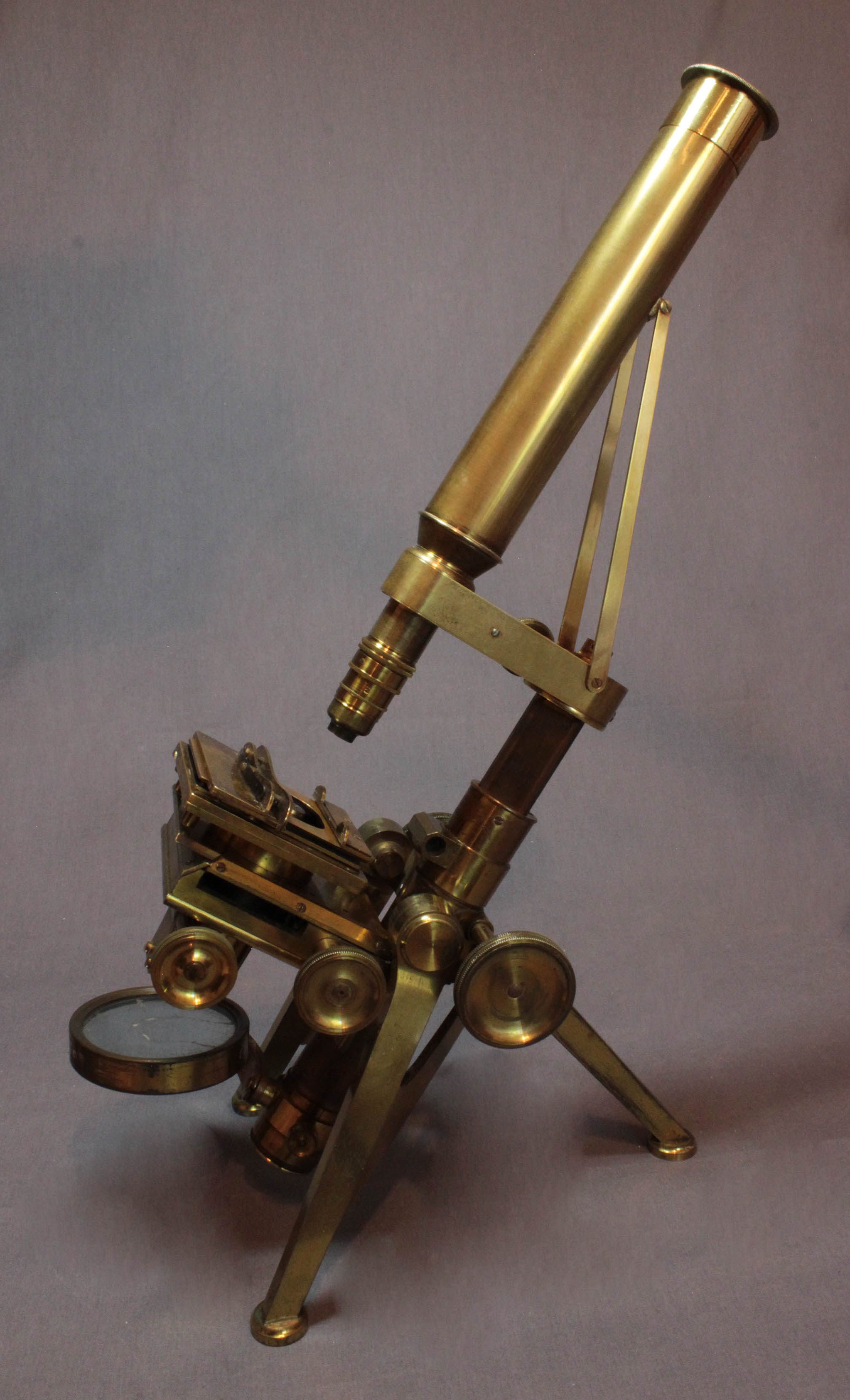
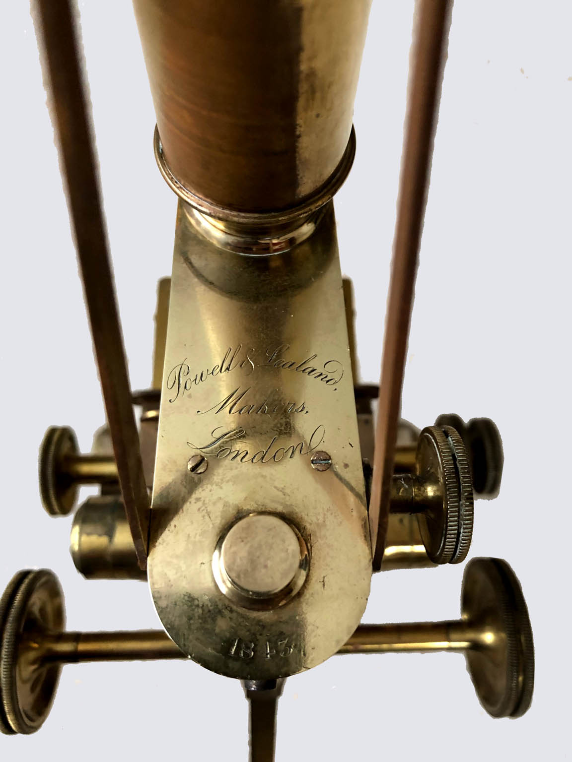
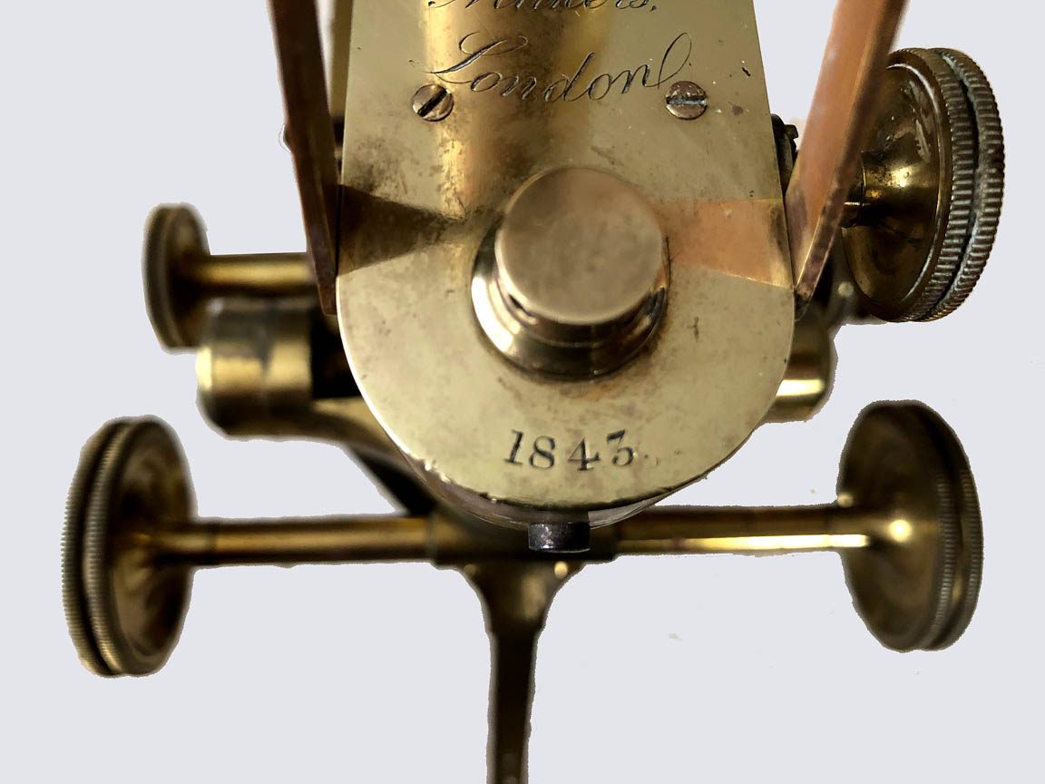 This microscope is signed and dated on the arm:
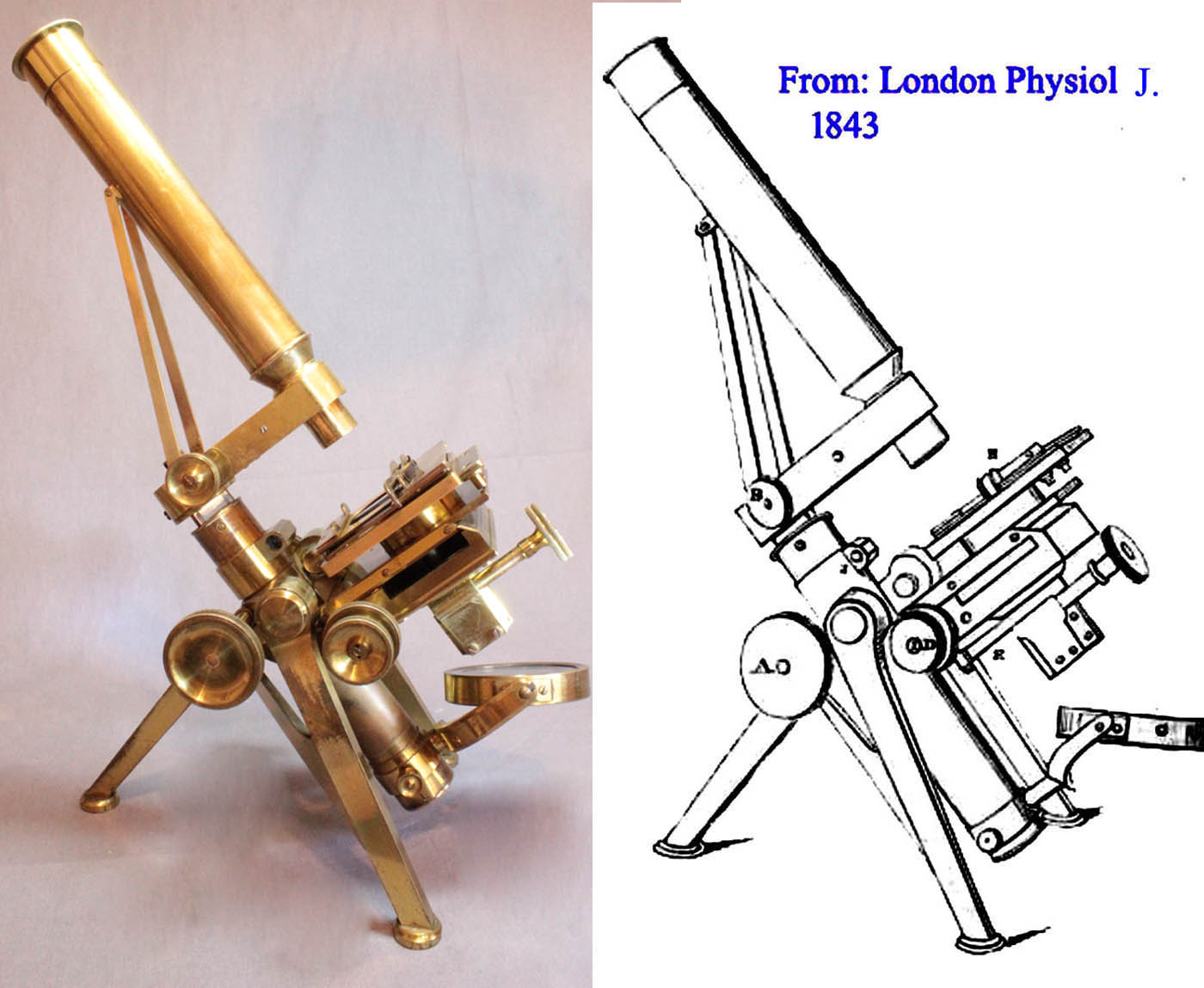
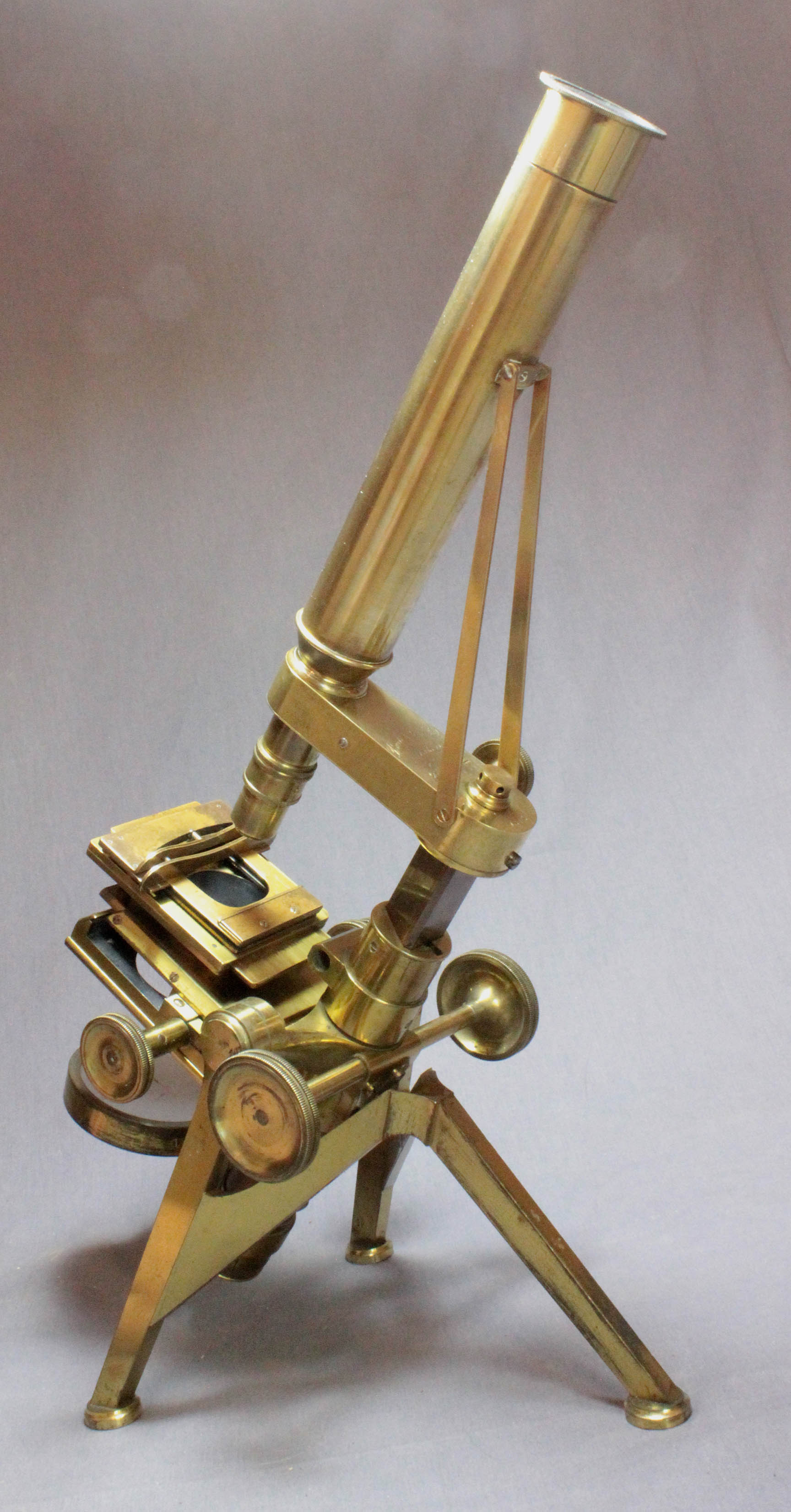
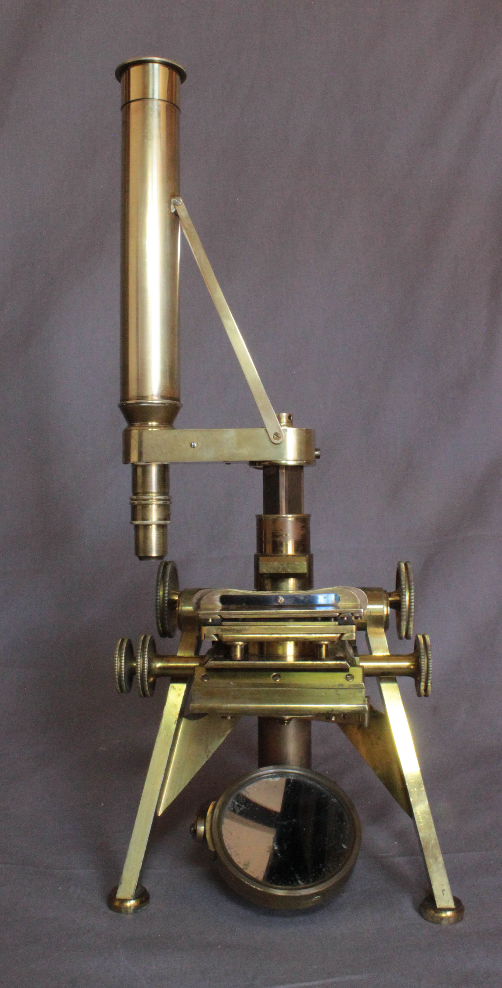
 Powell & Lealand, Makers, London, 1843. It is supported o what has become to be known as an
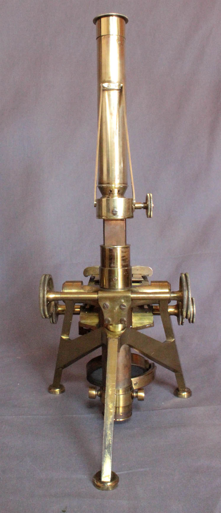
English tripodfoot with a span of about 16 cm (6.5 in.) right to left, and 20 cm (7 7/8 in) from either front leg to the rear leg (outside edge to outside edge). Each foot pad is of round profile and cork shod. On the later and larger models, including the Improved First Class Microscope, the No. 1 and No. 2, the pads were rectangular. Only the No. 3 retained the round pads.
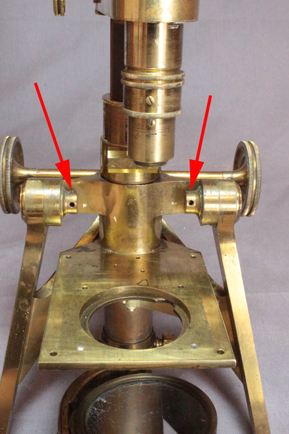
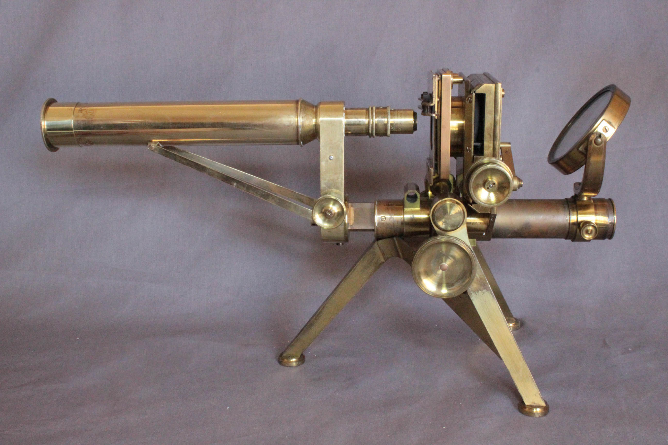
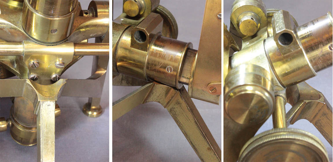 The right and left feet extend to support the microscope on trunnions, one on each side. The tension on these can be changed by adjustment screws on the inner side of each (red arrows); these screws have holes drilled thorough them to allow adjustment from the side using a small rod or Tommy Bar. The height of the axis of inclination is 127 mm (5 in.) from the table. The top of the rear leg of the tripod has a curved contour matching the round limb to fix the microscope in the horizontal position, while the inner surface has a curved contour to fix the microscope in a vertical position. This tripod foot was to form the foundation for P & L microscopes for many decades.
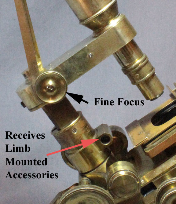
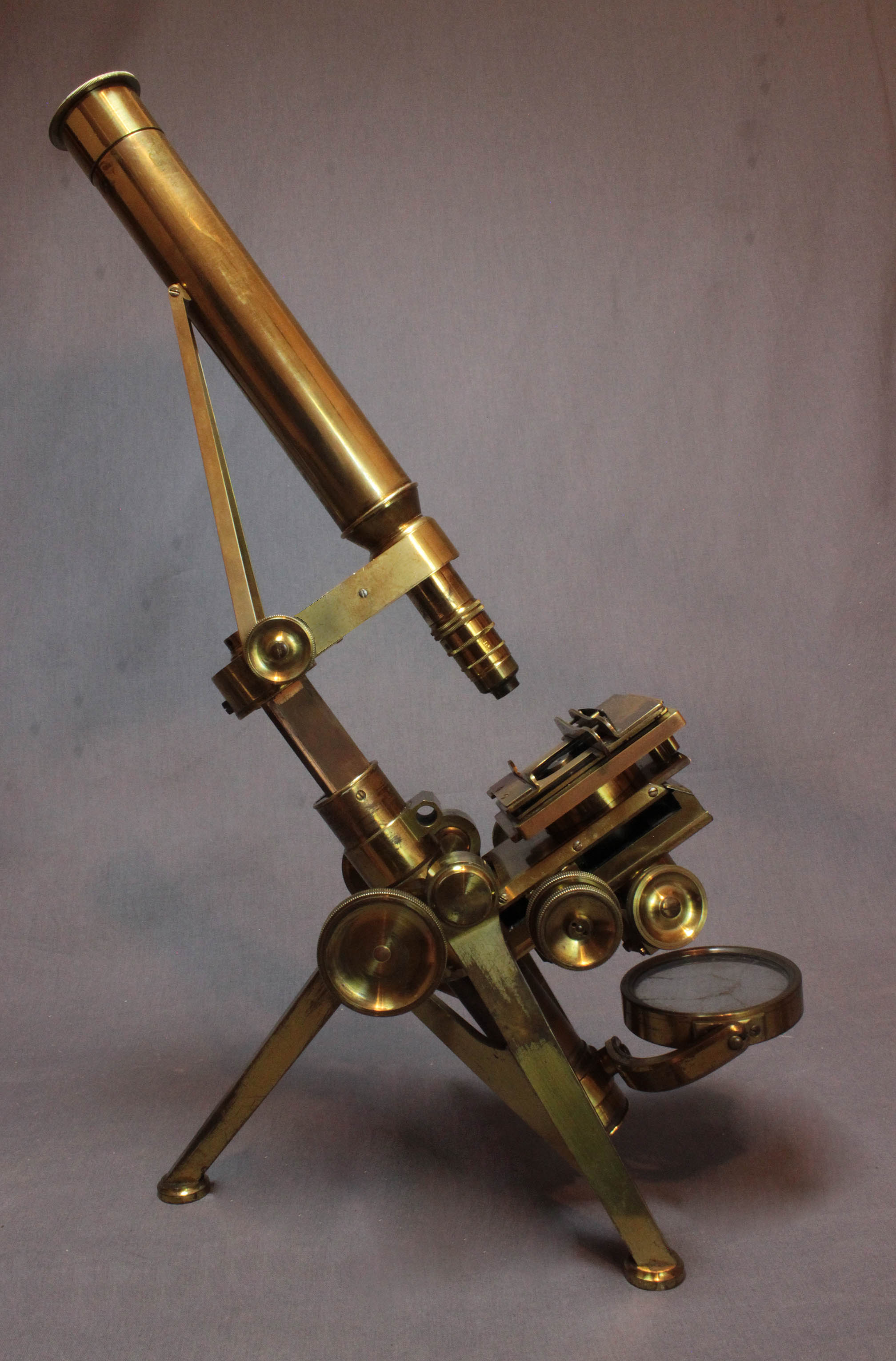
 The bar-limb construction features an arm that can be turned aside 90o clockwise where it reaches a stop. There is also a stop in the normal forward position. The tension of this swiveling motion can be changed with the adjustment screw on top; like the ones for the trunnions, this screw has holes drilled through it to allow adjustment from the side using a short metal rod as a lever. Coarse focus is by straight rack and pinion. Fine focus is by a horizontally-oriented knob on the right side of the arm acting on a wedge inside the arm to move a long lever to the nosepiece.
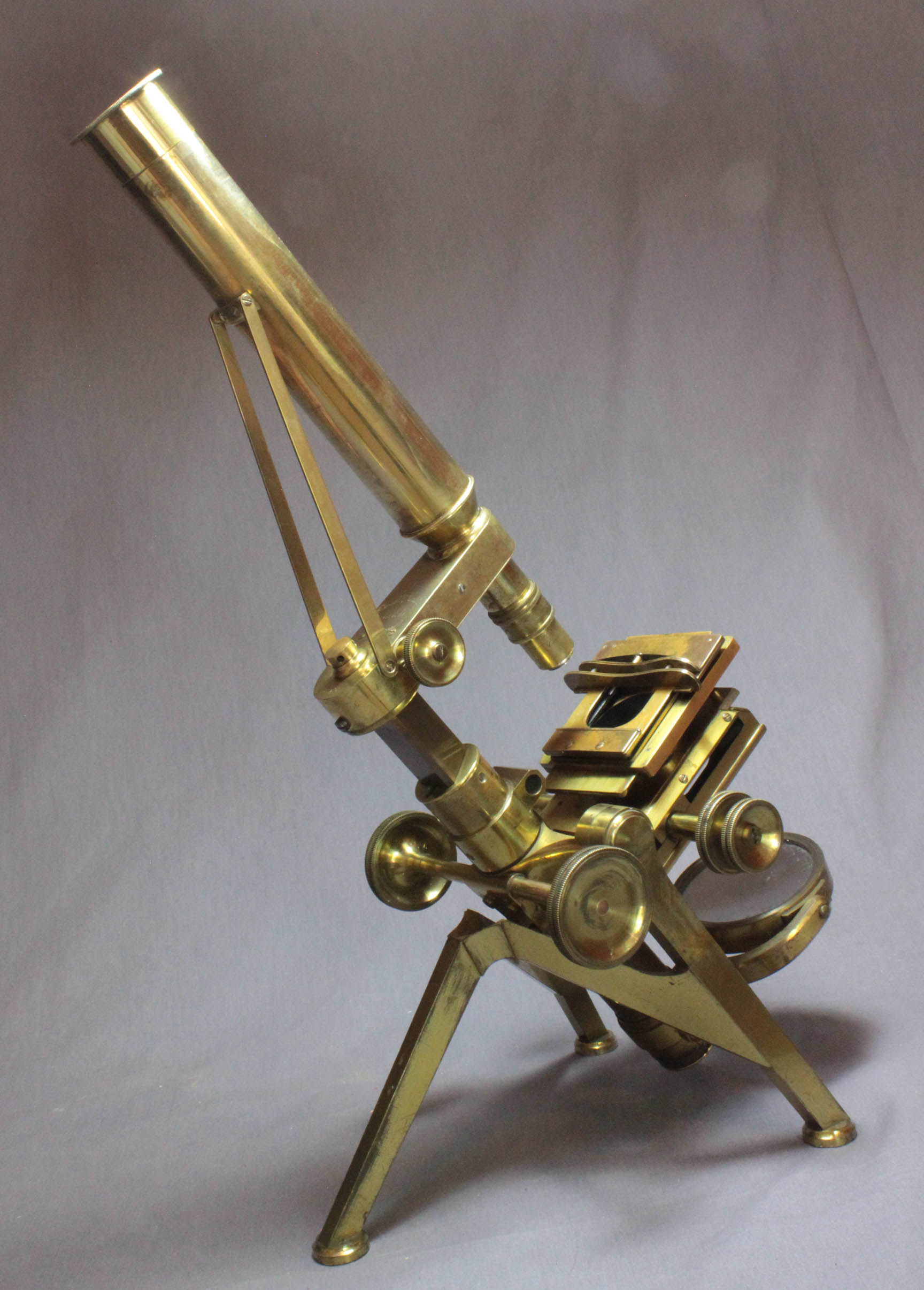
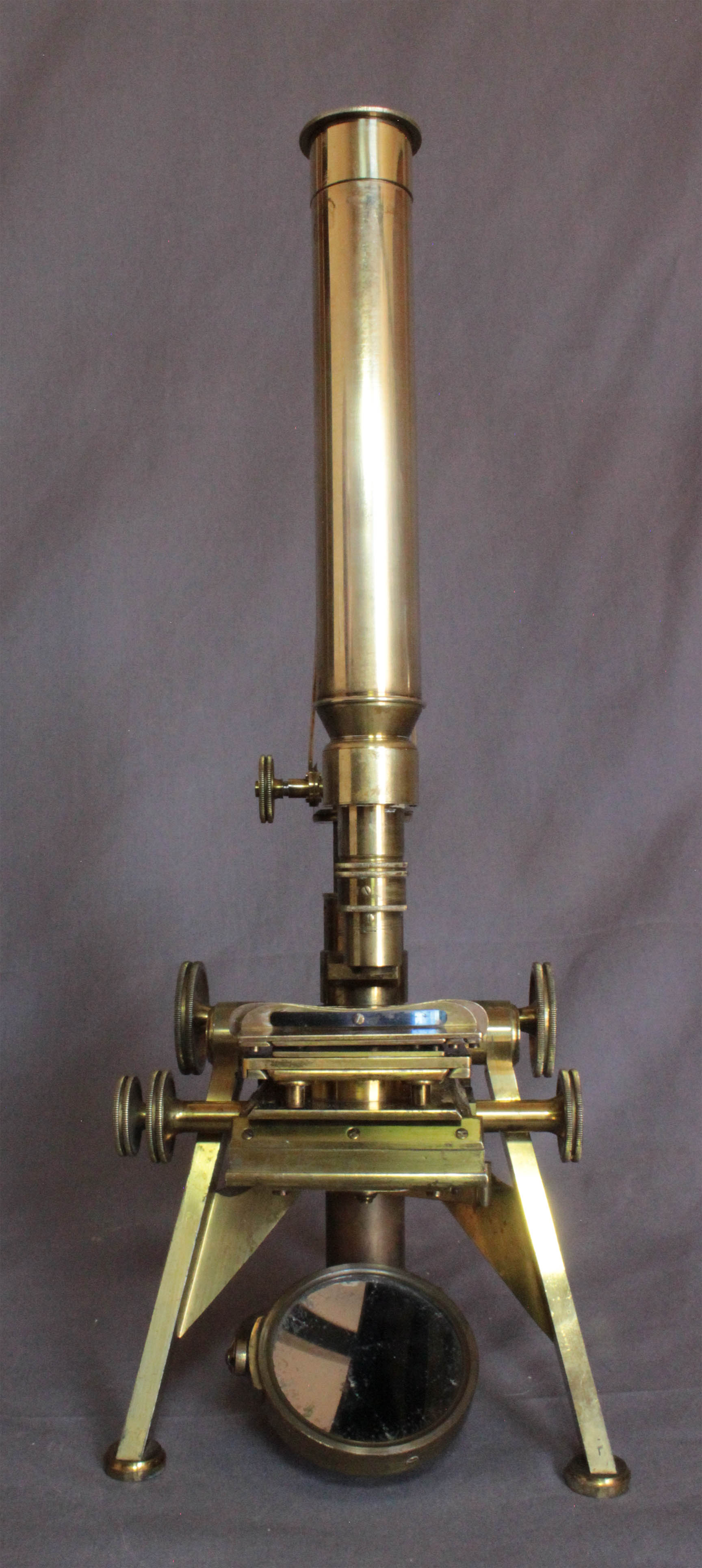
 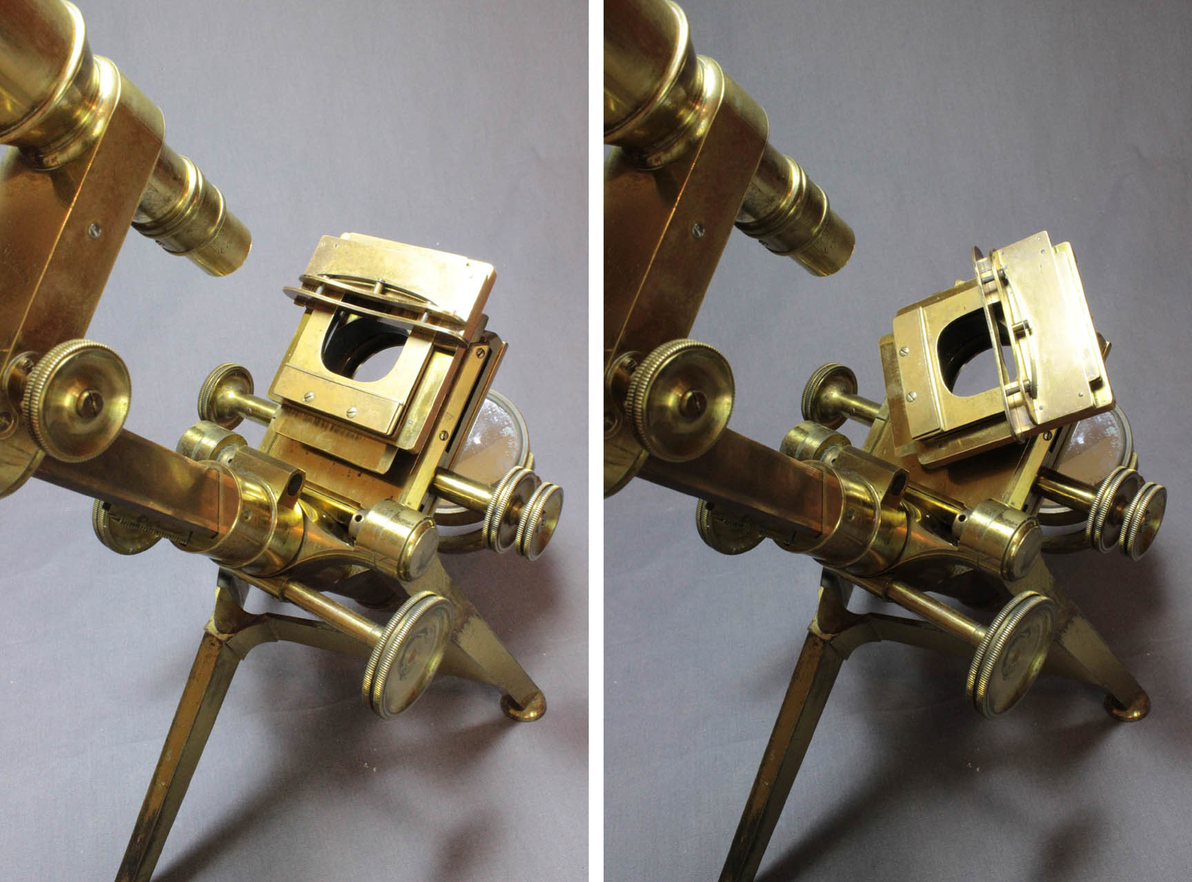 The mechanical stage is of the type invented by Turrell, with concentric controls. This allows right-left motion along the X-axis, back-and-forth motion along the Y axis, or, when both knobs are turned simultaneously, diagonal motion. The movement along the 'X axis' (right-left) is obtained through a spiral groove, known as a *constant lead cylindrical cam-and-follower design. The movement in the 'Y' axis (forward-backward) is by rack and pinion. A detailed description of the internal workings can be found on the mechanical stage page. The mechanical stage is held on a firm stage plate with by four screws from below. The slide being studied is held in position between one fixed and one sliding bar, on a sliding top stage plate assembly. The movable bar has a sprung pressure-plate, that presses against the edge of the slide to hold it in place. The plate that the upper double-plate slides on can be rotated by hand.
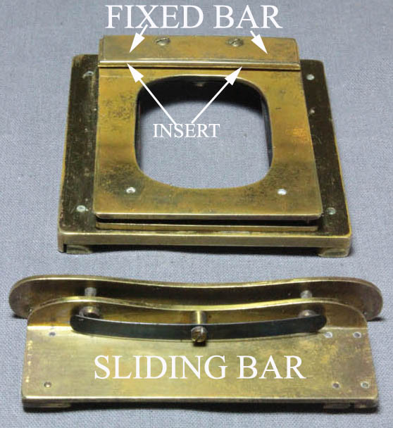
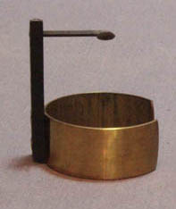
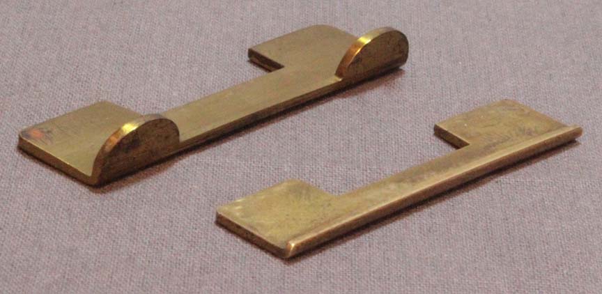 The fixed bar is raised above the surface of the plate by a piece of brass in the center of it. This brass spacer is not rectangular, being narrower in front than in back. As a result, a removable brass insert, which serves as a slide rest, fits in only from the front of this fixed plate, filling in the spaces on either side of the central piece. This arrangement would allow the insertion of an accessory slide-holding piece when the piece inserted is removed. Such a piece accompanies the accessories with this microscope and features tabs to the right and left side that were higher than the shallower insert, for securing thicker types of slides, troughs, etc. The two different inserts are shown to the right.
 screwdoes not drive a nut but rather the follower, a spring loaded V-shaped piece attached to the moving part of the stage.
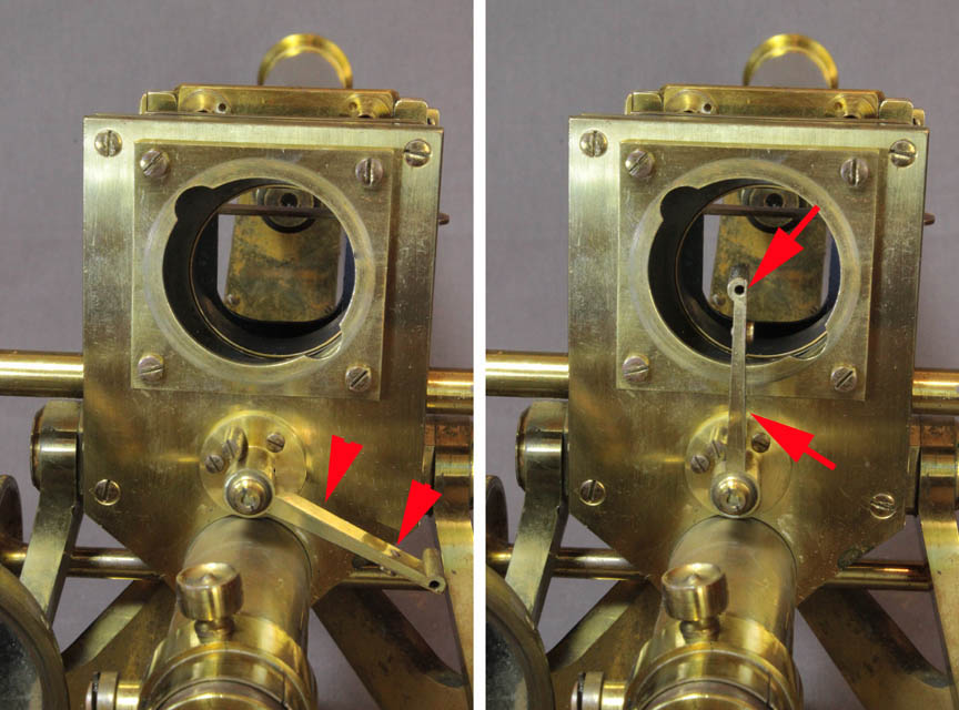
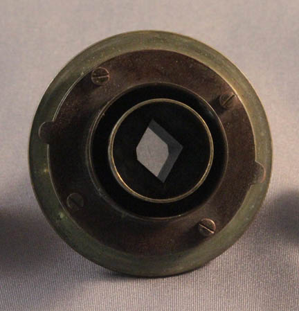
 The underside of the stage has an attached plate with a circular aperture havig opposed notches that accepts the male bayonet fitting on the larger substage accessories. An achromatic condenser assembly is shown mouted to this plate in one of the illustrations at the top of this page. Also under the stage, is a swing-in holder for darkwells (red arrows), very similar to the system used later by J.B. Dancer, among others. The user has a choice of three different diameter dark wells that fit into this holder. With the set are two of the same size for a total of four. The largest diameter dark well is shown installed in the image to the right.
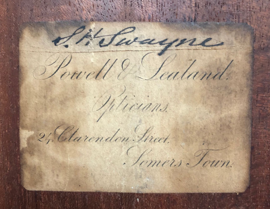
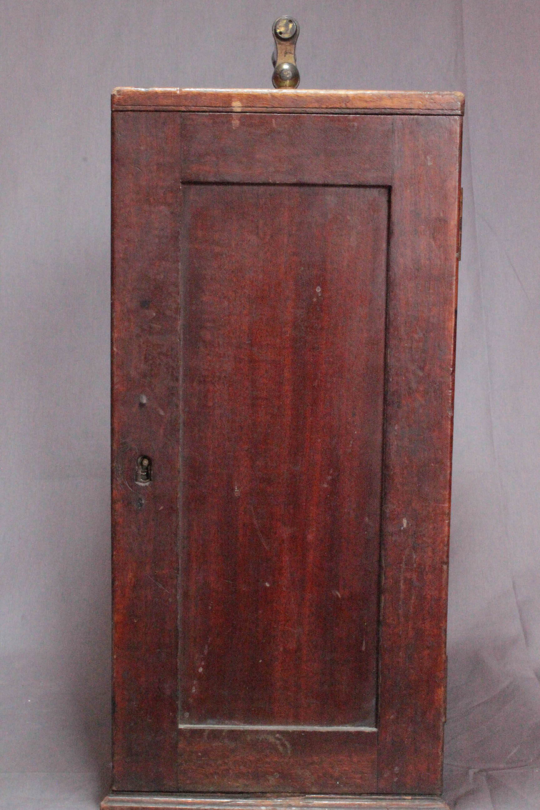 The original case (right) features the trade label (left), pasted on the inside surface of the door panel which reads:
 Powell & Lealand, Opticians, 24 Clarendon Street, Somers Town. This was the address of Hugh Powell when he was working alone from 1831 to 1841 as well as that of the partership, Powell & Lealand until 1846 when they moved. At the top of this label is written in pen and ink: 'S.H.Swayne', almost certainly the original owner.
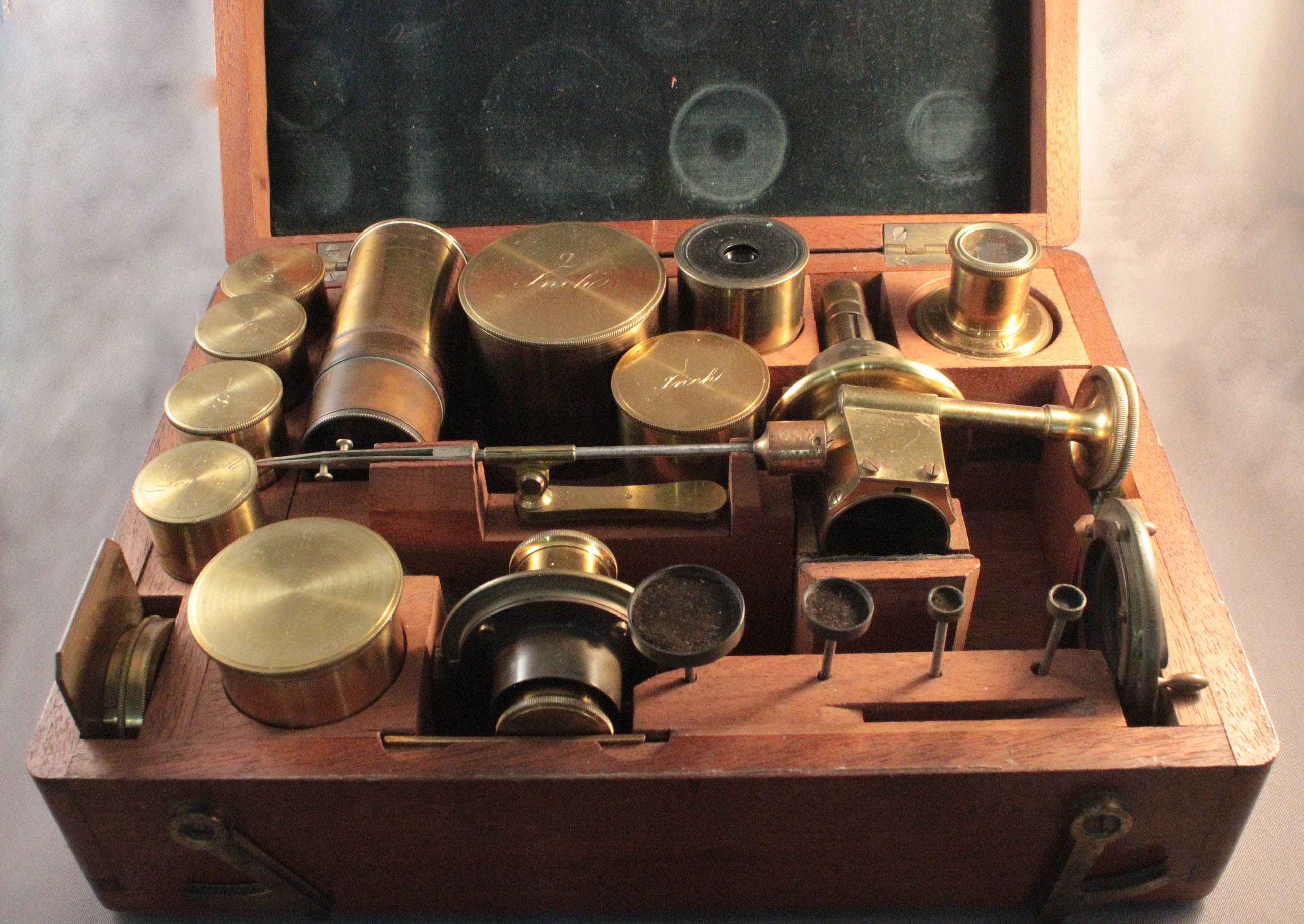
Originally this microscope would have come with a removeable box inside the main case to house most of the accessory parts. The accessory box now with the microscope is probably from another example of this model since it does not fit inside the main case. However, all the accessories do fit this microscope perfectly, indicating they are suggesting they are indeed the correct ones for this instrument. The accessories with it at this time include: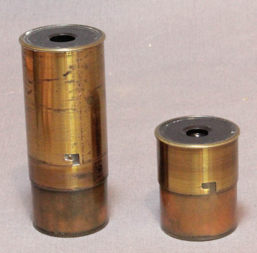
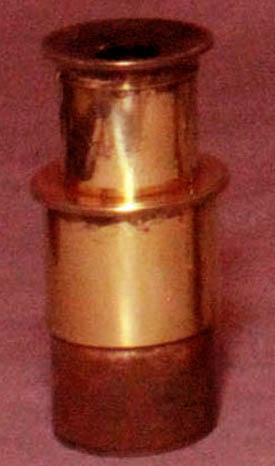 The eyepieces are cylindrical with flat tops which is the earliest form that came with this model microscope. They have removable eyepiece caps that locked into place via bayonet fittings. This locking device prevents the eyepiece cap from coming off when pulling the eyepiece out of the tube. The bottom portion of these eyepieces fit inside the optical tube while the upper portion of lacquered brass, which was the same diameter as the tube, projected up and at first glance makes the tube appear longer. The eyepiece caps are removeable and can be replaced with either the analyzer eyepiece cap or the camera lucida. As time passed, the style of ocular was changed to the familiar
 top-hatconstruction, shown to the right, which had become so common in England and remained so for rest of the century. However as shown in the image, the P & L top-hat oculars differed in still having a polished section below the lip that remained exposed above the end of the microscope tube.
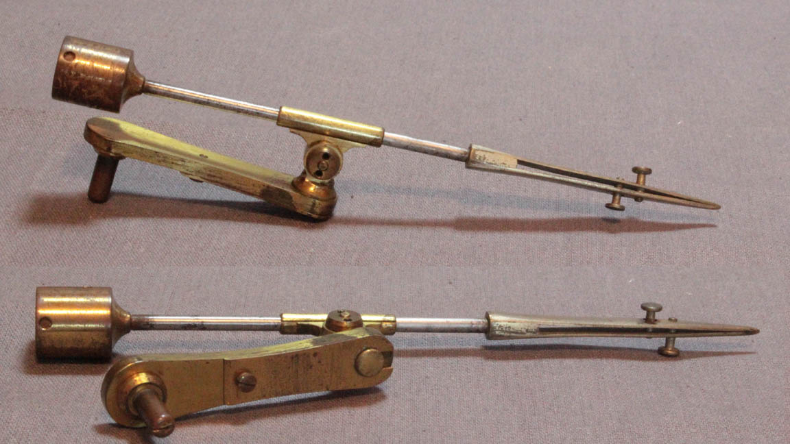
 The Soemering-type camera lucida, right, also replaces the cap on either eyepiece. This device has a highly polished silver reflector which redirects the image in the eyepiece up to the eye of the user while the microscope is in the horizontal position. The diameter of the reflector is such that it is supposed to be smaller than the average pupil in a darkened room. In this way, the image is seen superimposed on the drawing paper.
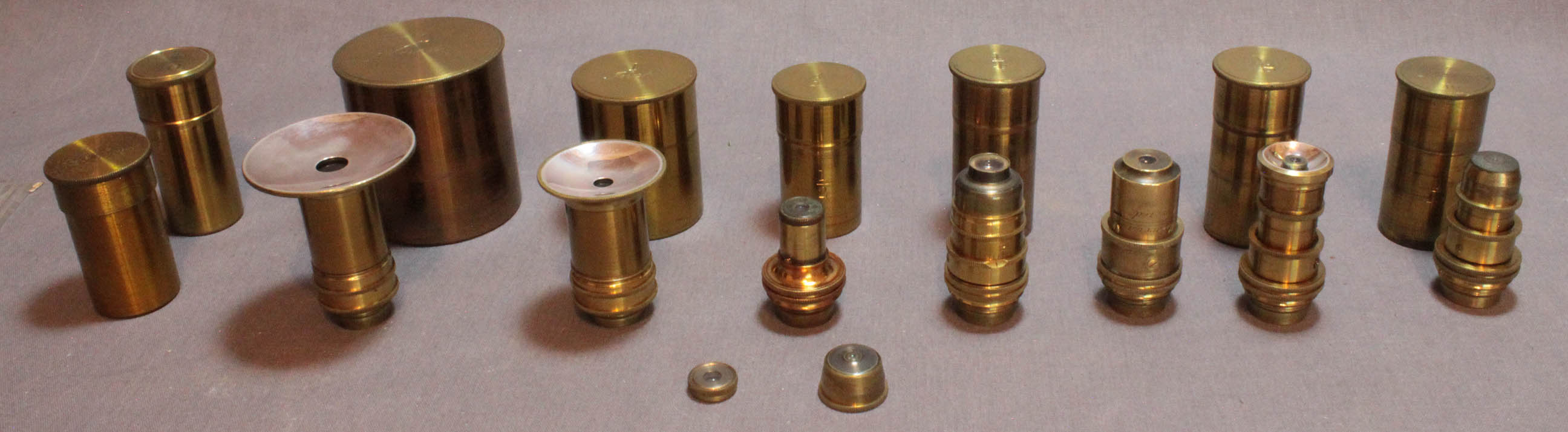
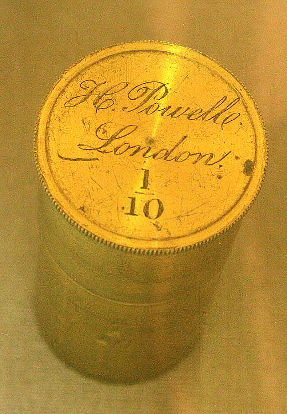 There are seven objectives with the instrument. None of the objectives themselves is signed as was usual for the objectives made by both Hugh Powell alone and also by Powell & Lealand. These include the five in the accessory box, and a single objective without original can which came attached to the microscope. There is also a 1/10 inch Hugh Powell objective, the highest power objective, (obviously made by Powell before the partnership with Lealand in 1842), which comes in its original can signed:'H. Powell, London, 110. All the objectives were made with a mounting thread predating the standard RMS thread, and so were designed to fit only the microscopes of P & L; they would likely not fit others without an adapter. The objective range was wide even then, and included those with correction collars for high power work such as four of the objectives with this instrument, including the 1/10th inch objective by Hugh Powell shown here. Three of the objectives have Lieberkuhns and they store attached to their respective objectives. Other than the Powell example, the cans are only labeled with the focal length of the objective contained therein. There are also two objective fragments. One of these has a very tiny lens and clearly, at one time must have attached to the distal end of a high power objective.
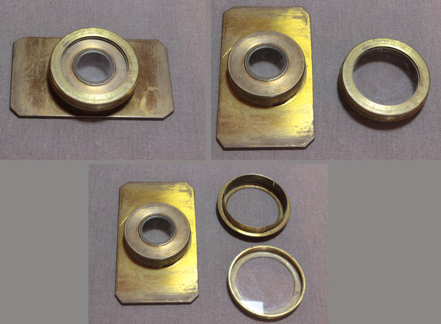
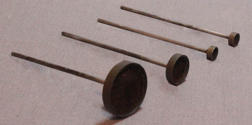 Three dark wells were most likely always supplied for this microscope, fitting into the permanently attached substage dark-well holder. A fourth was added to this kit in the past, but is also a P & L type. The P and L darkwell page also illustrates how these are used with the microscope.
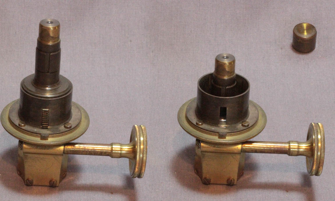
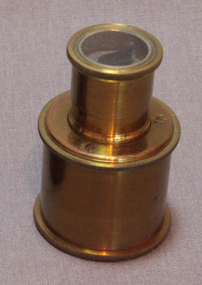
 Of particular interest are the substage accessories for use with transparent objects. When these microscopes were first made, a condenser for use with high power objectives was provided with the instrument (left). Because the stage is quite thick, the tube of this condenser has to be relatively long. To be able to focus it, the rack and pinion apparatus had to control it from below the underside of the stage. No control of aperture of this condenser, intended for high power work, was provided. For lower powers, a separate wheel or disk of stops was also provided (right). Both of these pieces of apparatus have lugs to allow installation via the bayonet fitting under the stage, but only one or the other can be used at any one time. The substage condenser is supplied with a dust cap for its top. With the substage condenser the flat side of the mirror is used. When using the microscope without the substage condenser, the curved side of the mirror is used.
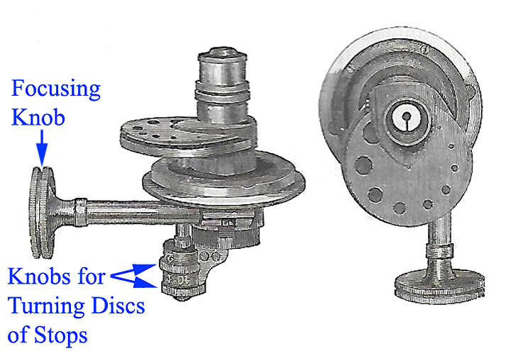
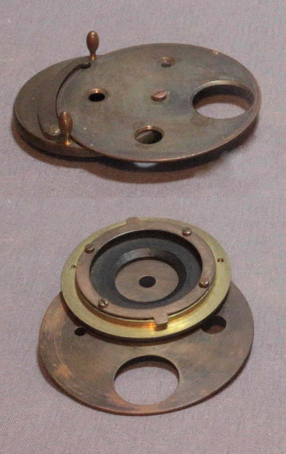
 By the 1850s, as shown in the illustration to the left from the 1856 volume of Carpenter's The Microscope and Its Revelations, a more complicated condenser could be supplied. It provided built in stops. To achieve this, it not only had to attach to the underside of the stage by a bayonet fitting, it had to be able to fit inside the deep stage so its top lens could approach the bottom of a slide. To accomplish this, the stops were spread over two disks or wheels, thereby reducing the size of the disks so they could fit into the relatively small opening in the bottom of the stage. Furthermore, the entire apparatus had to be adjusted from below, by controls projecting below the bottom of the stage. The two controls for the wheels of stops were concentric and there were markings to indicate which stops were in the optical path. This anticipates, to great extent, and was undoubtedly the inspiration for, the later substage-mounted Ross Improved Gillette Condenser. The rack and pinion focusing of this P & L condenser was also controlled by a knob on a fitting protruding below the understage mounting. Although rack and pinion substages were being added to the larger transitional P & L models no later than 1856, the integrated rack and pinion substage was not used on this smaller size of microscope until the No 3 model came into existence in the 1860's.
 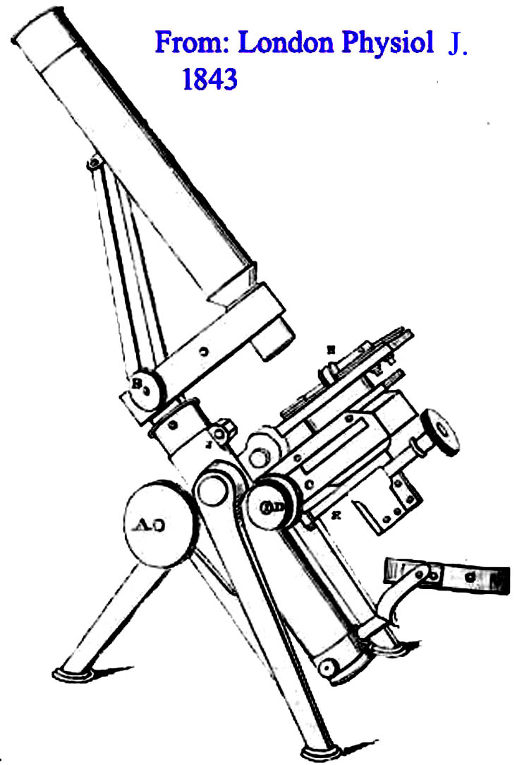 Although larger model microscope stands had been produced by Hugh Powell, notably the massive stand commissioned by the Royal Microscopical Society in 1840, what is now known as the No 1 Model was a direct development of Powell & Lealand s 'New Microscope' of 1843, the model featured at the top of this web page. These microscopes of 1843 formed the prototypes of the famous group of stands, later to be called the Powell & Lealand Number 1, Number 2, and Number 3. In fact, this microscope is often confused with the later Number 3 stand, which it resembles in many ways. As shown here, this form of stand was first described in the 1843 November issue of The London Physiological Journal as 'Powell & Lealand s New microscope'. This stand is supported by a lighter, but still very strong, version of the tripod, than P & L's later first class stands. It carries the body on trunnions, and has a transverse arm, which contains the long lever connected to the nosepiece. Initially, as seen on this example, the fine-focus screw, which operated on a wedge, was placed on the right side of the arm. The mechanism was revised to utilize to a L-shaped piece instead of a wedge, starting in 1844. The mechanism was changed to the familiar vertical position on the top of the arm starting in 1848 and 1849. In those years some microscopes still had side fine adjustments. From 1850 onwards, the fine adjustment was only found on the top of the arm. At this point in its development, the microscope tube was also supported by a set of diagonal stabilizing struts extending from the back of the arm to the upper third of the tube. Sometime during the early 1860's these were abandoned.
 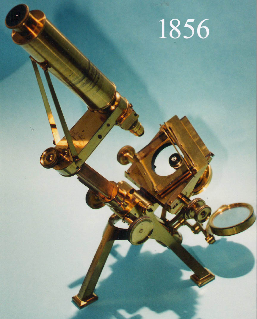 Powell & Lealand did not enter the 1851 Great Exhibition, but it is believed that during this time they worked on a larger model based on the original design. Dated examples are extant from this period, with the more solid rectangular feet as in the later No 2 stand, either with or without the supporting struts. These could be regarded as the 'proto-No 1/No 2 stands', from which the later models were developed. Two examples of these, called the
 Improved Large First Class Microscopeare found on this site, and they still have struts supporting the tube. As seen in the image to the left, this stand of 1856, is essentially the same as the 1843 stand, other than the position of the fine focus knob, the design of a heftier tripod, and the rectangular and heavier tripod legs. More importantly though, it now had a separate rack and pinion substage, so substage accessories no longer were attached to the bottom of the stage itself.
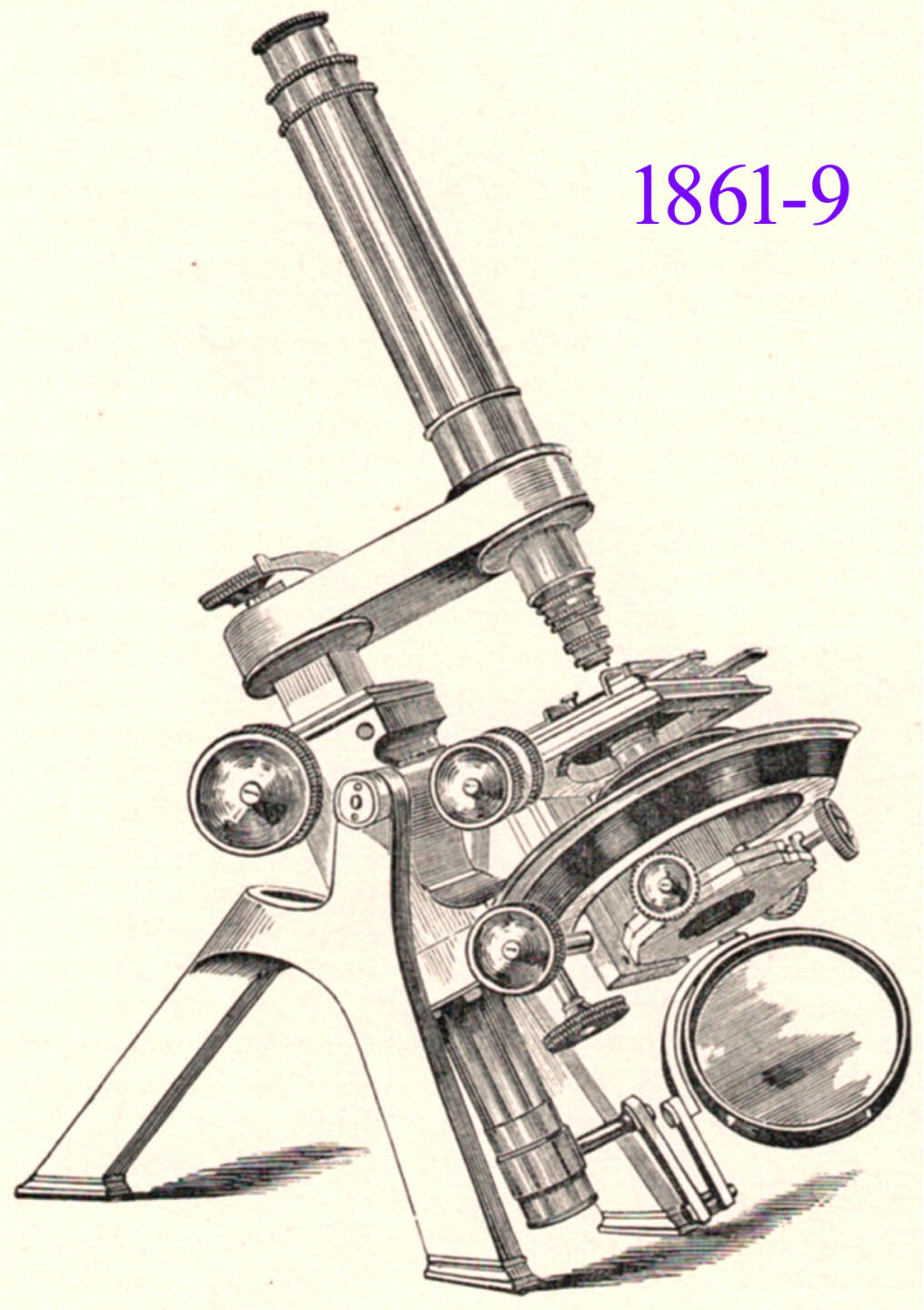
 The next model, shown here, was worked on at odd times, and appeared in 1861. It was similar in outline and appearance to the final No 1 design, save for the massive ring attached to the limb, within which there was a second ring carrying the stage to which the substage was attached, allowing both to be rotated by the same rack-and-pinion movement, with separate rotation also provided for the substage. An example of this model was ordered by the Radcliffe Library for use by The University Museum, Oxford, in 1864, together with a 1/50-inch objective amongst the accessories. We should also note that Wenham's binocular, first seen about 1860 was added to the Powell & Lealand options and further improved upon over the years. The No 1 model continued to be made as described above until the definitive version of the No 1 model stand was put on the market in 1869. The main modifications involved the construction of the rotating stage, which this time was mounted in the same plane as the ring, and there was a separate carrier for the centering and rotating substage, attached below the stage now, and not rotating with it as in the previous model.
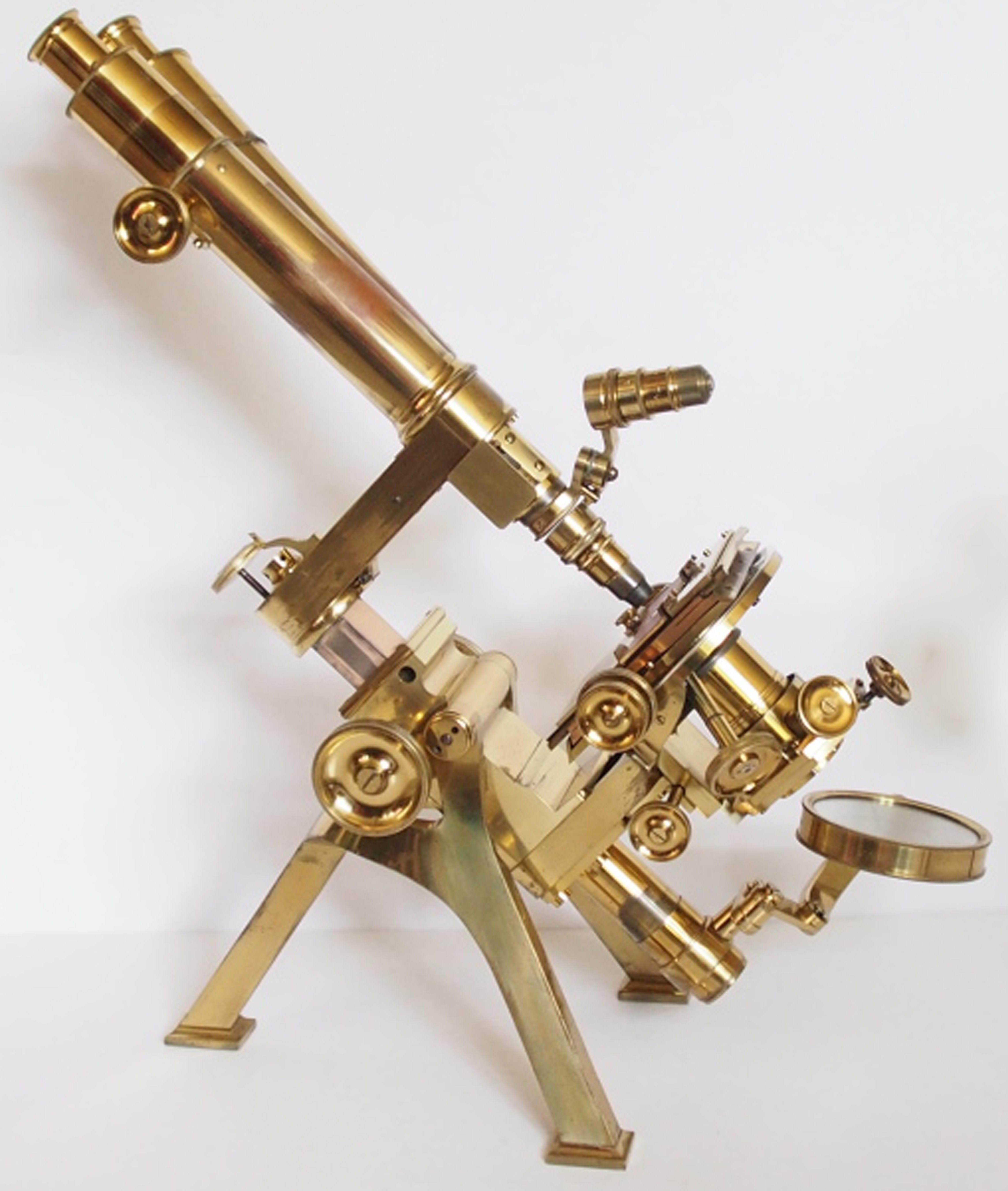 In this final form, the Powell & Lealand No 1 microscope continued to be made unchanged for another 40 years, until the firm quietly faded out of existence during the first decade of the 20th Century. The only additions, were an optional fine adjustment to the substage (1882), rack work to the monocular draw tube (1887), and diagonal rack work to the coarse adjustment, all at the suggestion of E.M. Nelson, an eminent microscopist, and user of this model. For more information about P & L, including a detailed and illustrated description of the final form of the No 1, as well as a more detailed history, please see the Powell & Lealand No. 1 page