Please Click On Any Picture for a Larger Version, where available
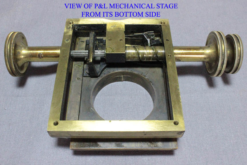
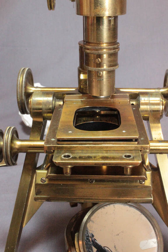
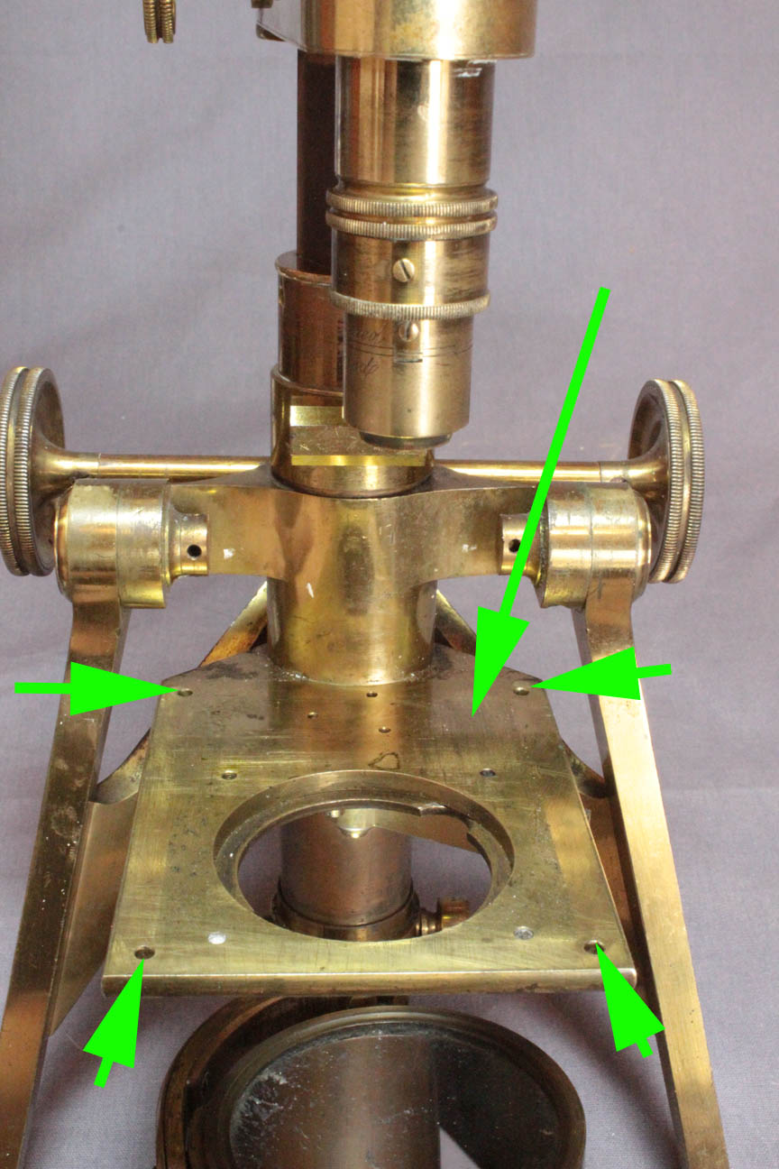 The entire mechanical stage is held on a firm stage plate(long green arrow) by four screws. The screws pass through holes in the corners of the stage plate(short green arrows), from below.
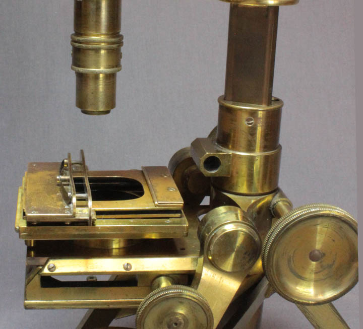 The slide being studied is held in position between one fixed and one sliding 'bar'(left) on a sliding double-plate which sits on the top of the mechanical stage assembly.
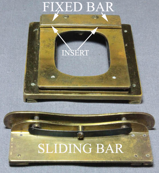
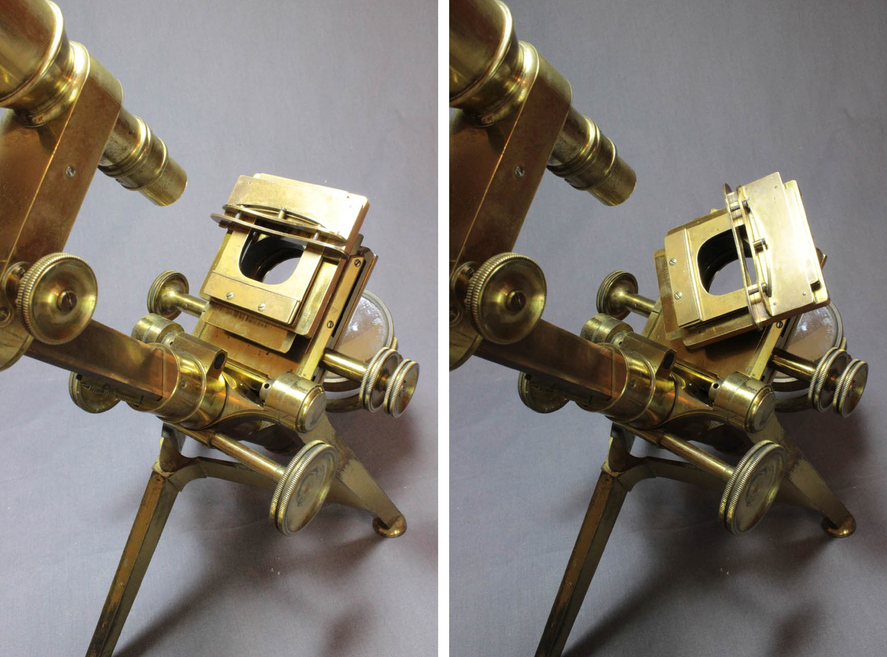
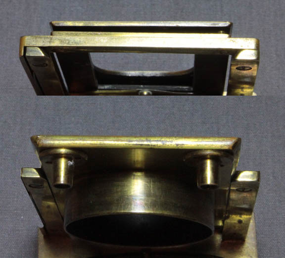
 As can be seen in the image to the right, the moveable bar has a sprung pressure-plate to hold the slide in position against the fixed bar.
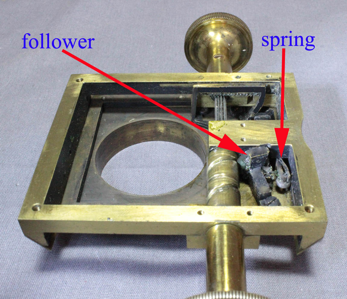
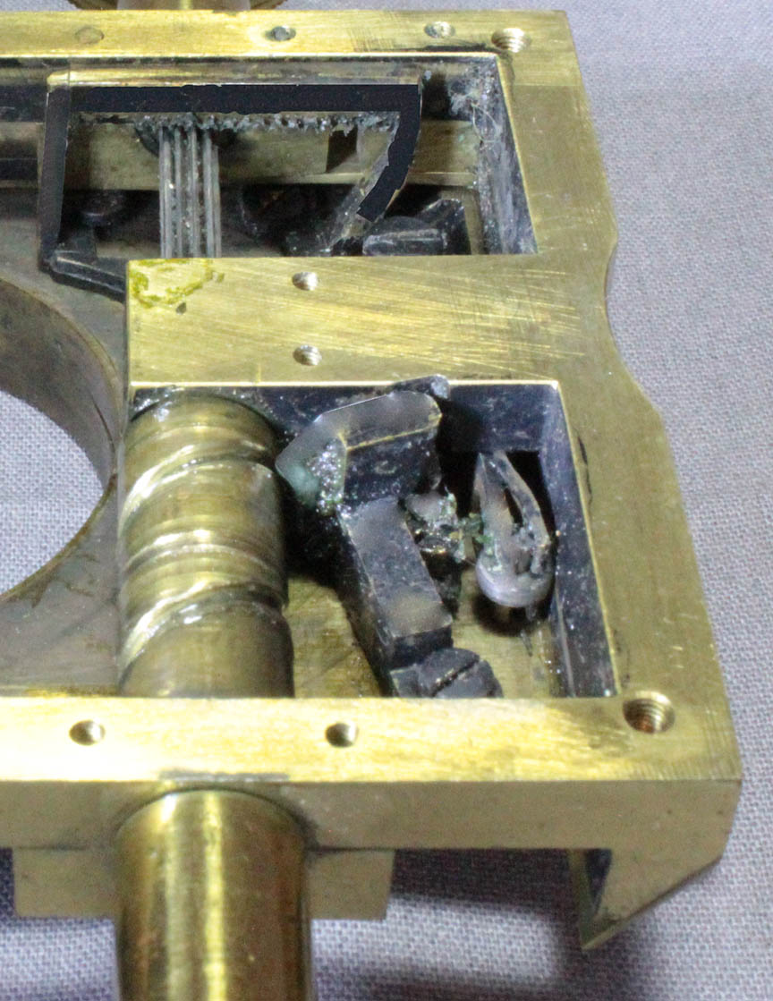
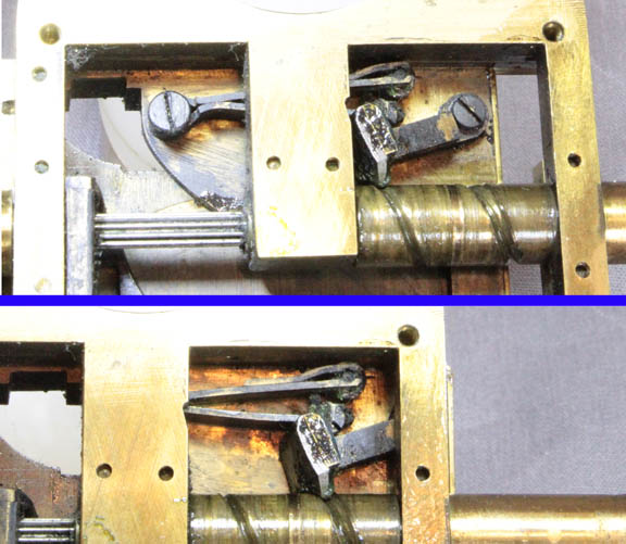
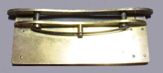
 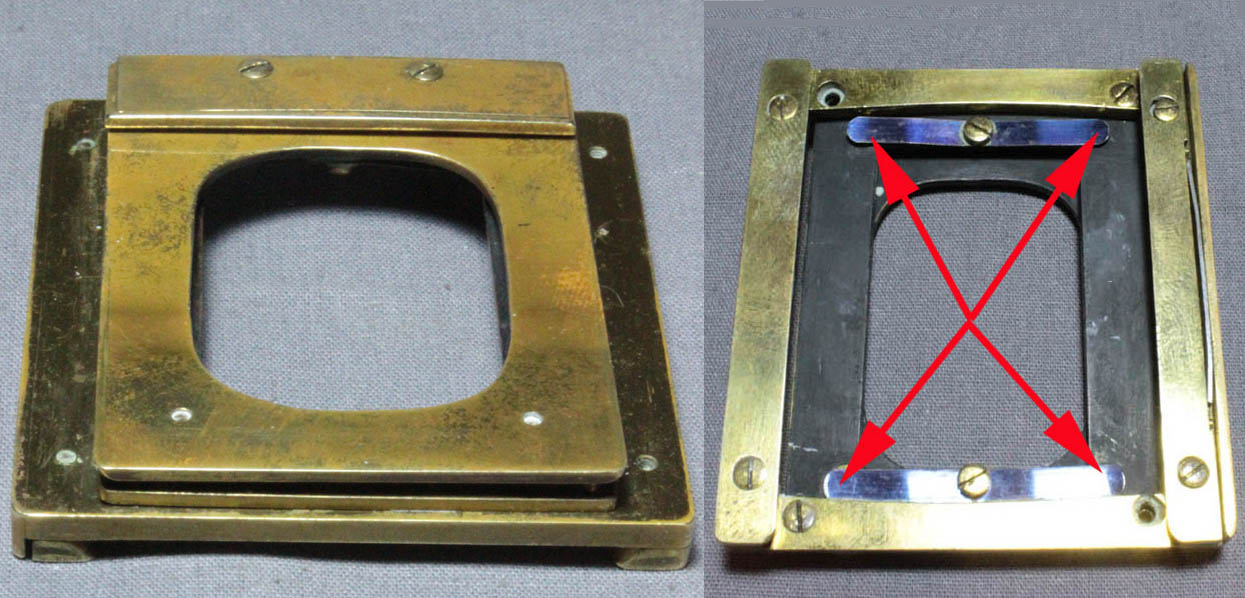 The top plate of the double-plate is pushed upward by a spring mechanism of the same type used for the pressure plate of the moveable bar shown above. This sprung mechanism then forms a 'safety stage'. This helps to ensure that if an objective is accidentally racked down on to the slide while focusing, the top surface of the stage gives way, downward. The top part of the double-plate has four small rods, one near each corner, which fit through holes in the lower plate. These rods have round cap-like ends resembling nails, preventing the upper plate from coming off. Attached to the underside of the bottom plate, are two leaf springs. The tips of the rods are held upward by the far ends of these two leaf springs. These springs are attached by screws at their centers to the bottom plate so that their ends push upward on the rods coming down through the holes in the lower plate; the ends of the leaf springs(red arrows), then give way when downward pressure is applied to the stage, preventing damage to the slide and/or objective.
 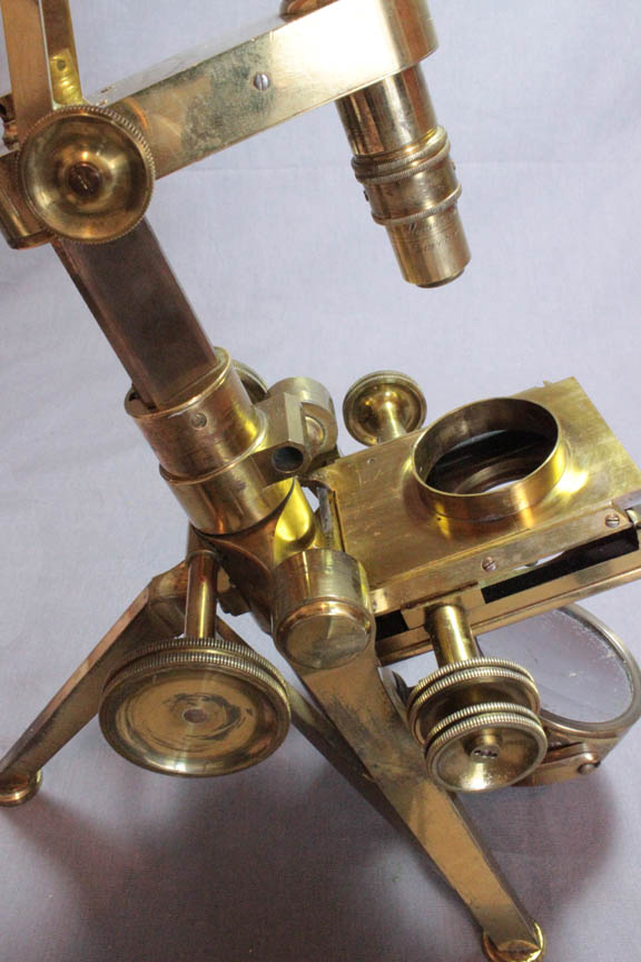 The controls of the mechanical stage act on a plate with a ring on top. This plate moves in dovetail guides.
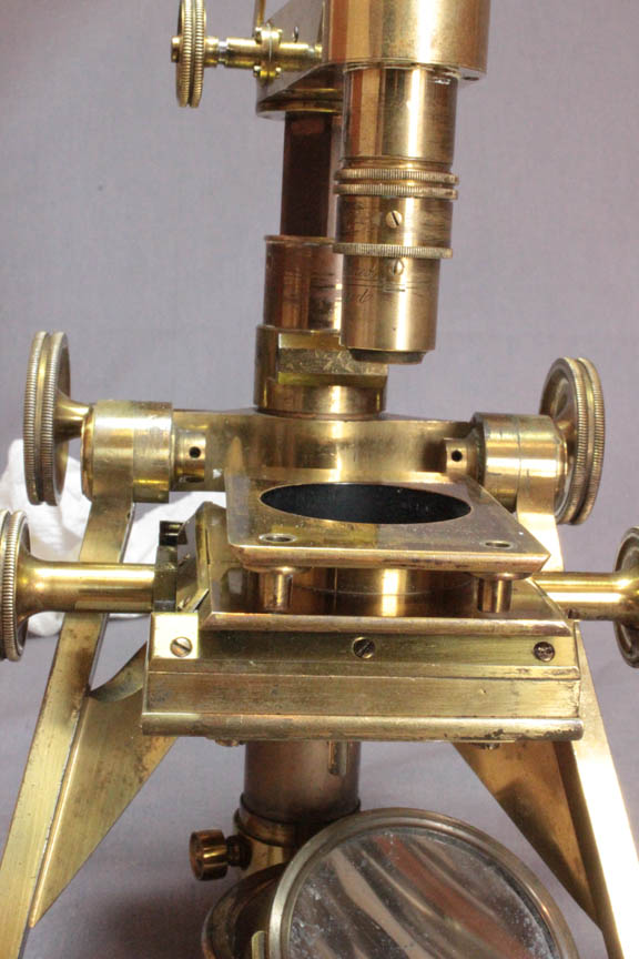
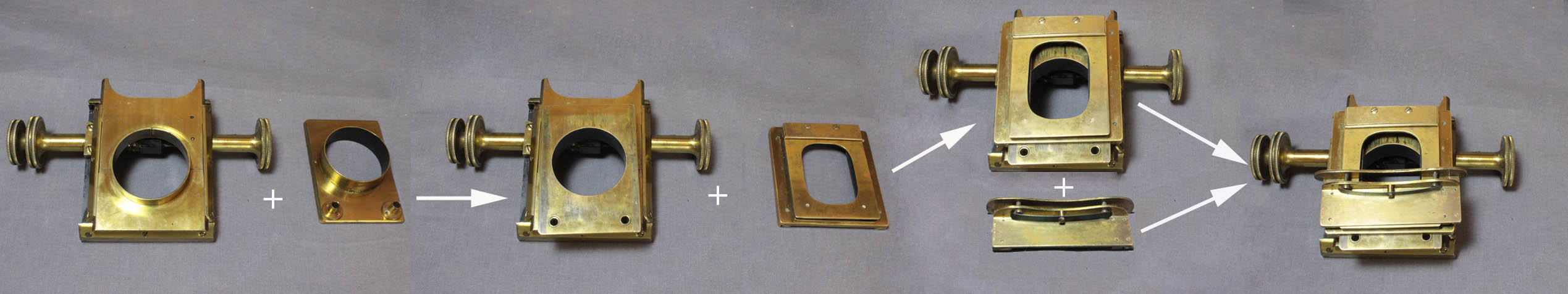
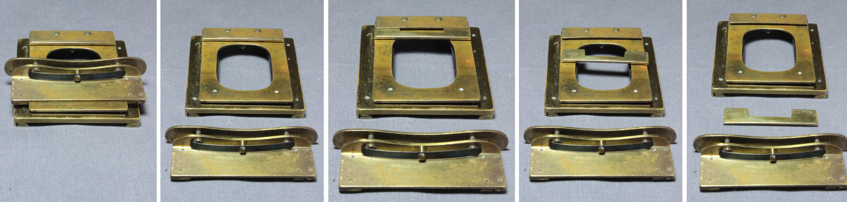
 The first part added on top of this plate is a rotating plate that has a round fitting on its bottom to slide down into the brass ring on top of the rest of the mechanism. Note the two holes with fittings on the bottom of the rotating plate to secure stage-mounting accessories like a stage forceps. After the rotating plate is in place, the next piece to be added is the sprung double-plate with a fixed slide rest. As shown to the right, it slides on via a sliding dovetail arrangement.
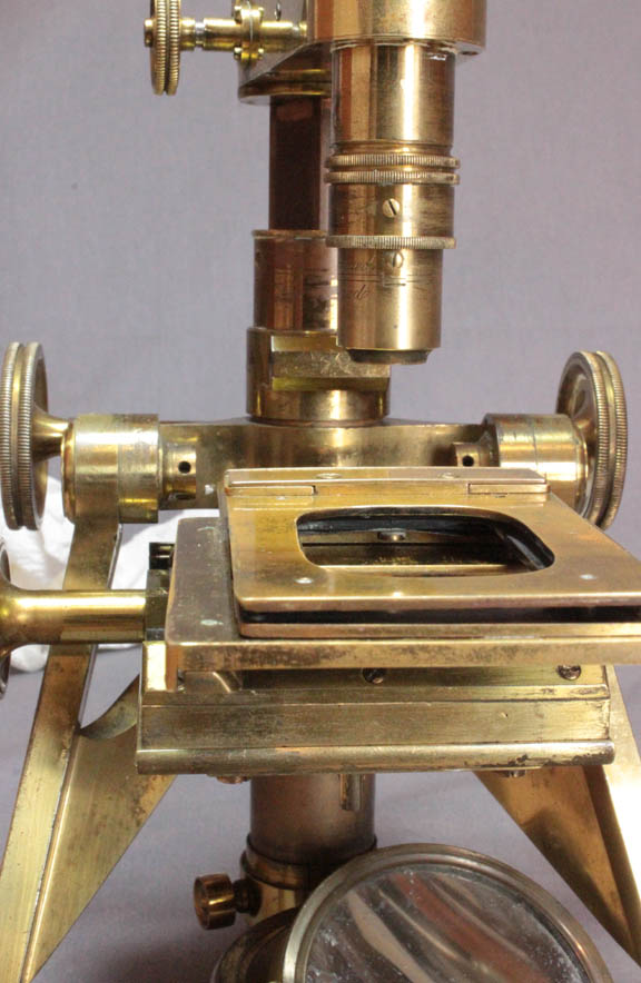
 As shown to the left, the double plate dovetails on to the rotating plate by sliding on from the front. When it is slid past the midpoint, as shown to the right, the two holes for accessories on the plate beneath it are revealed.
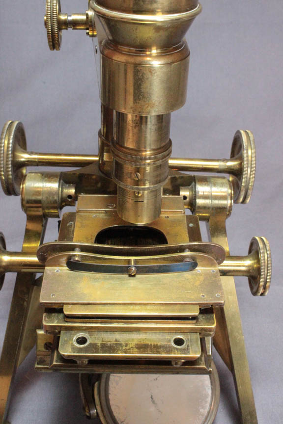
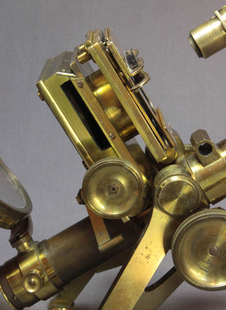 Finally, the moveable slide rest, or bar, dovetails on to the sprung plate to complete the stage. Notice how thick this arrangement is(right).