BAR LIMB COMPOUND MICROSCOPE
MAKER: ANDREW ROSS
MODEL: No. 1
c. 1847
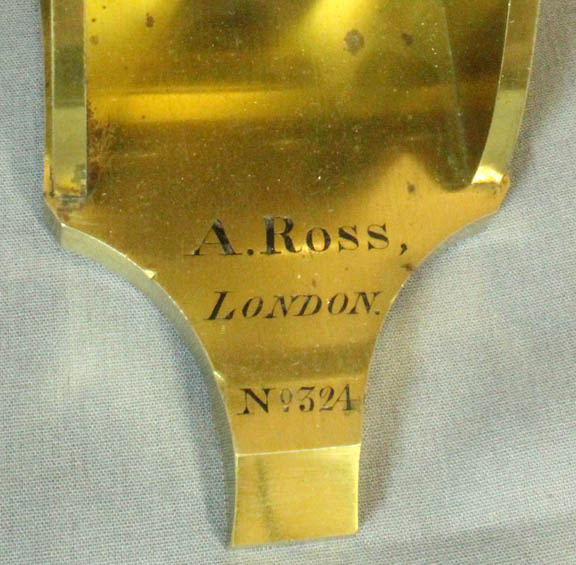
SIGNED: 'A. ROSS, No 324, LONDON'
Please Click On Any Picture for a Larger Version(where available)
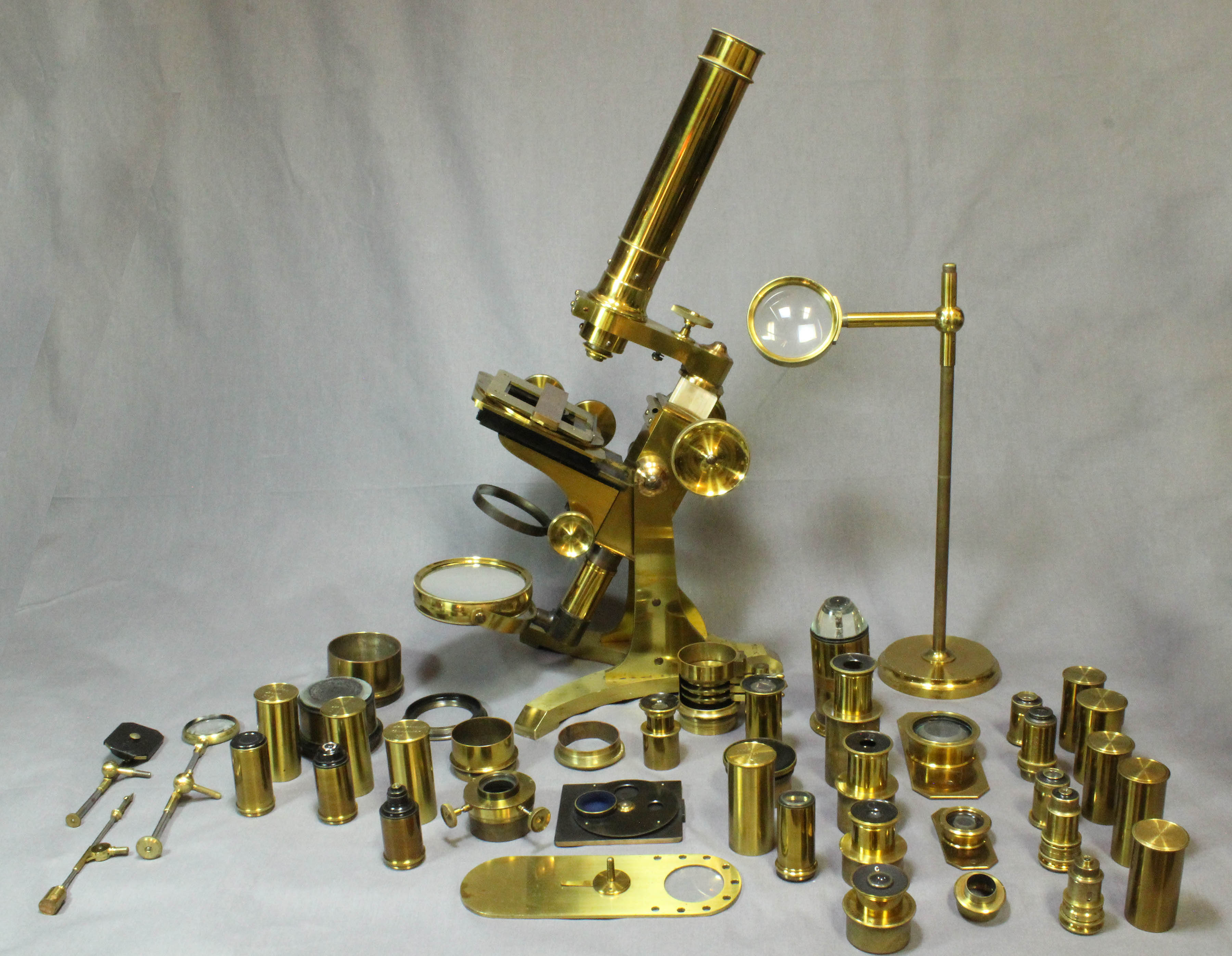
ROSS SETUP FOR POLARIZED LIGHT WORK
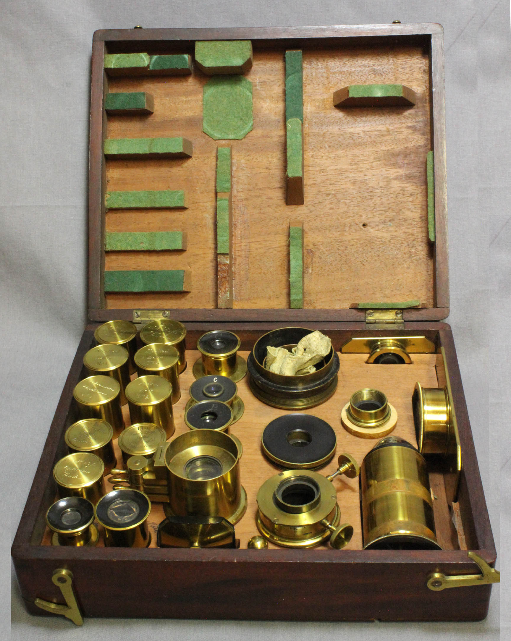
ROSS ACCESSORY CASE
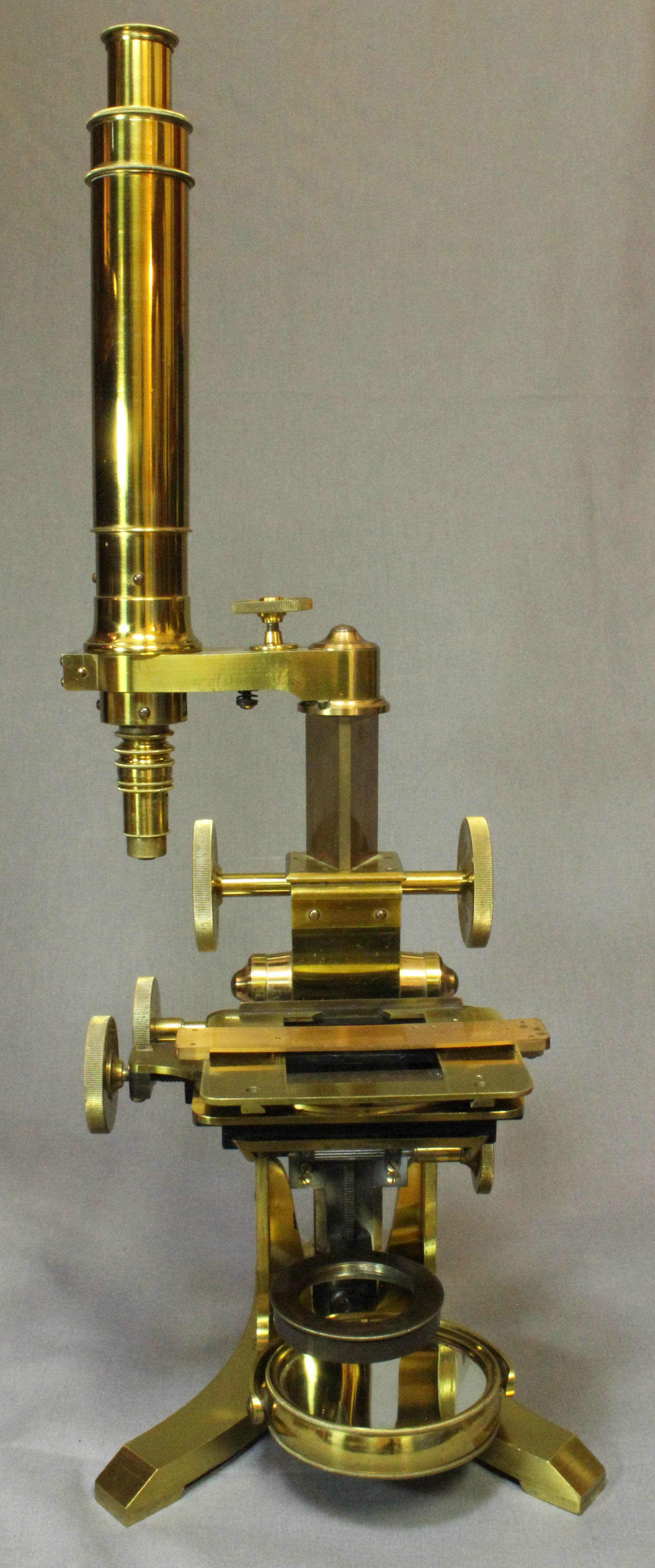
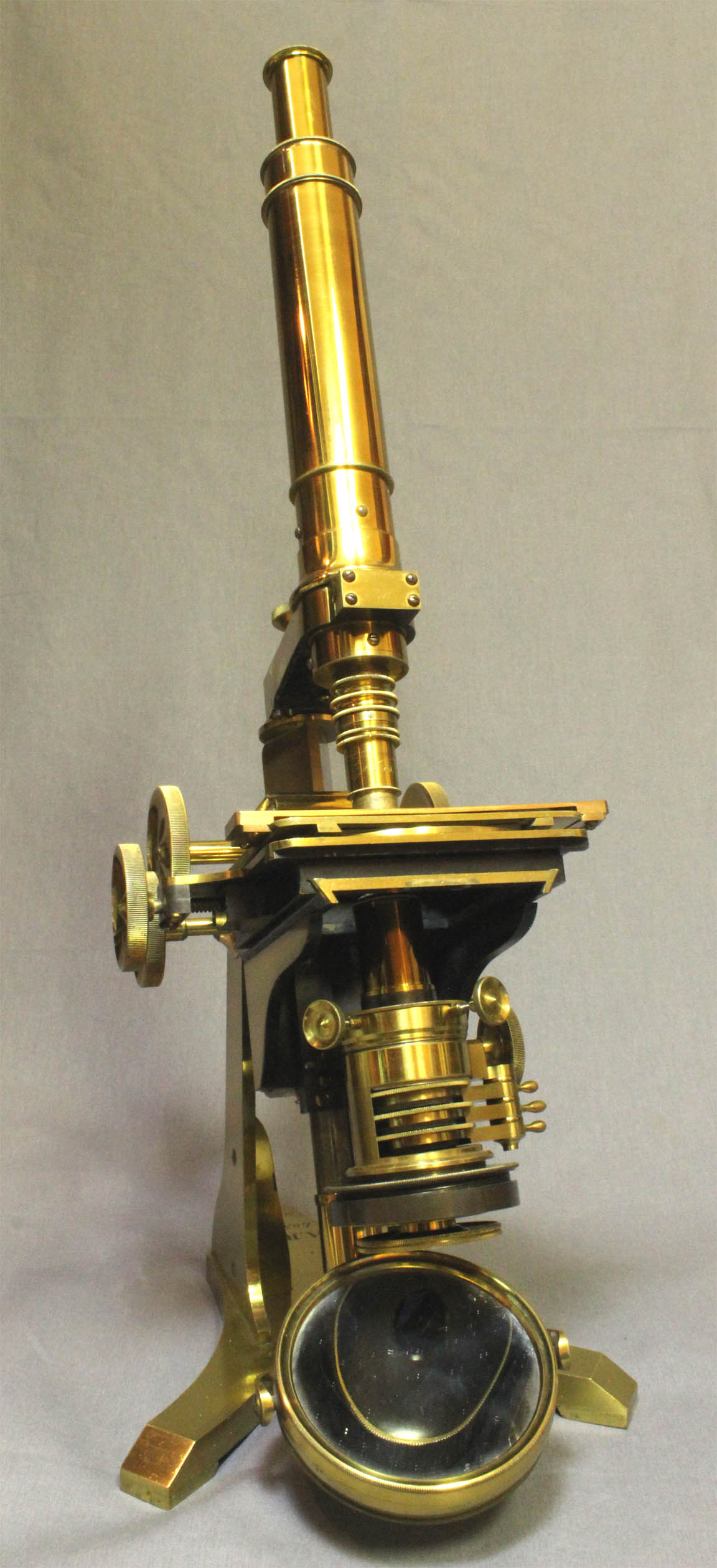
THE ARM CAN ROTATE 90o FOR BETTER ACCESS TO THE STAGE
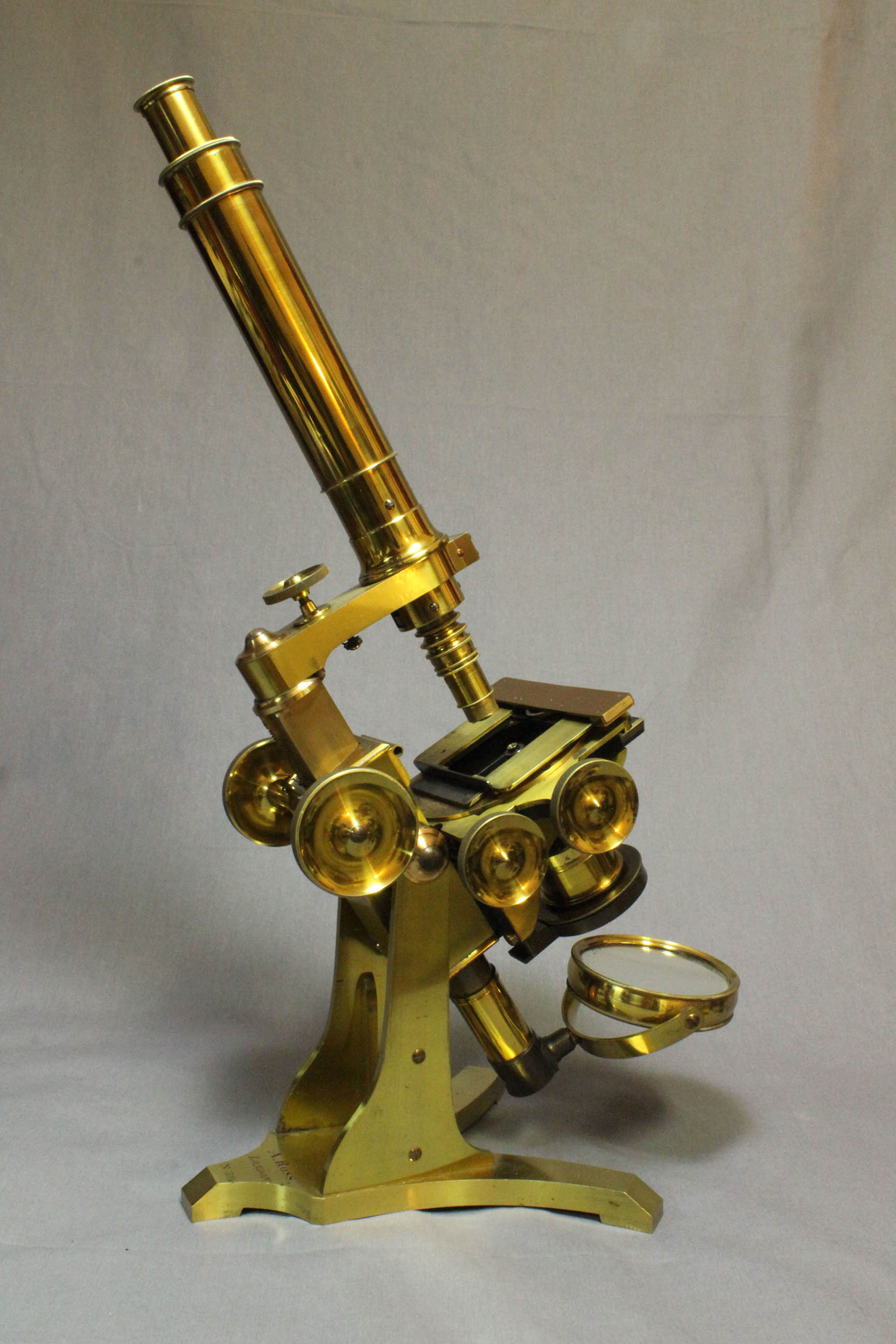
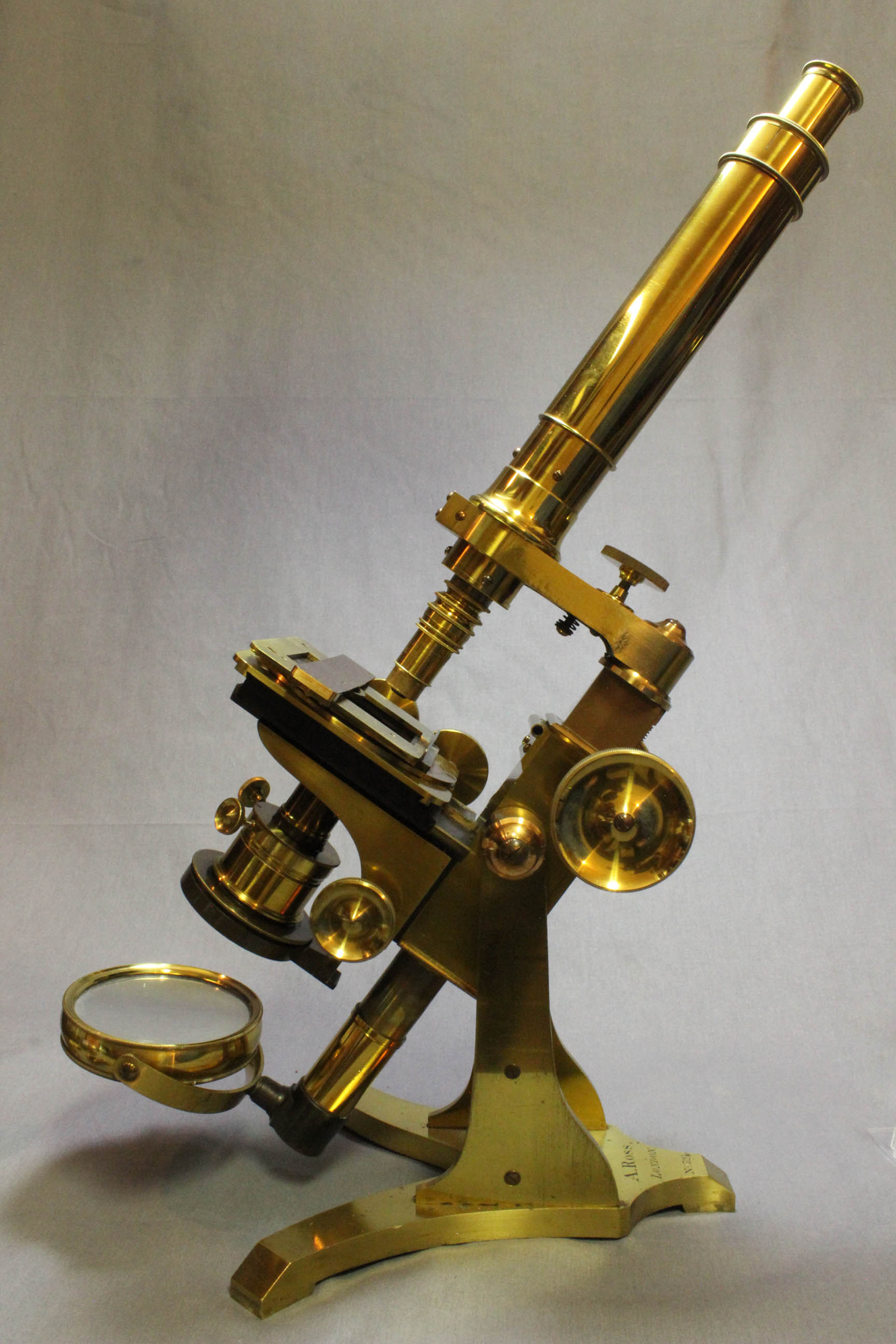
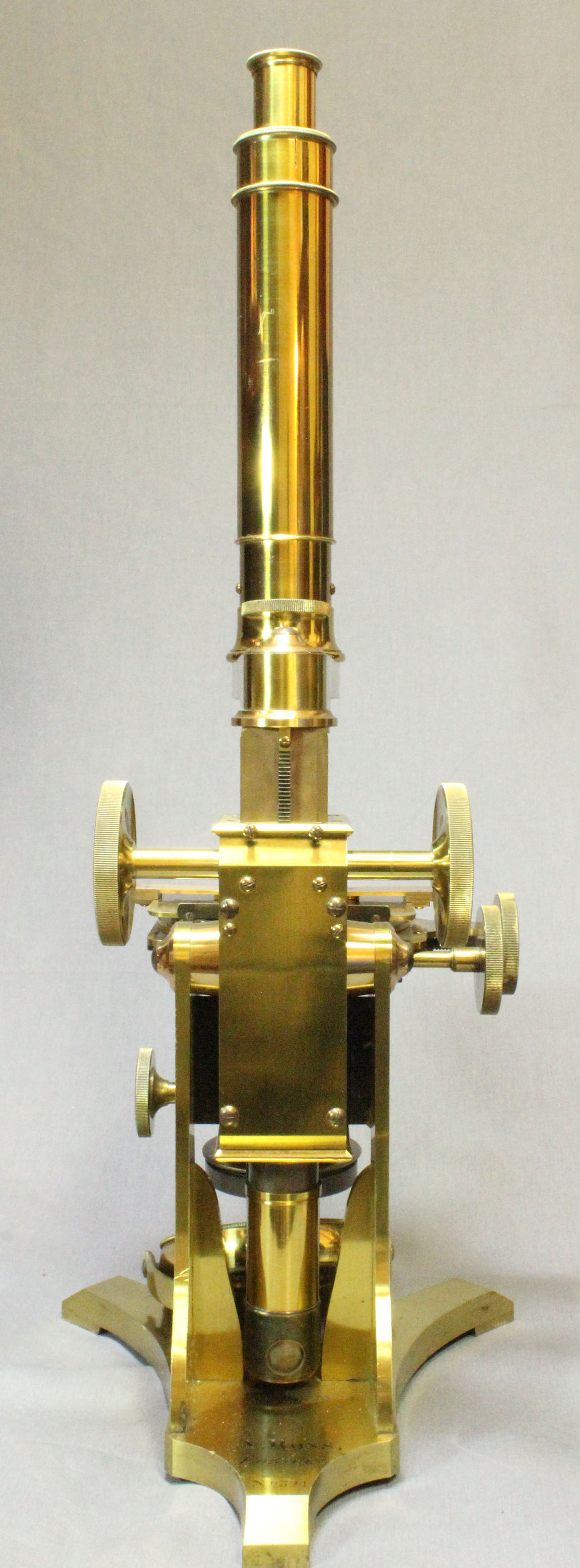
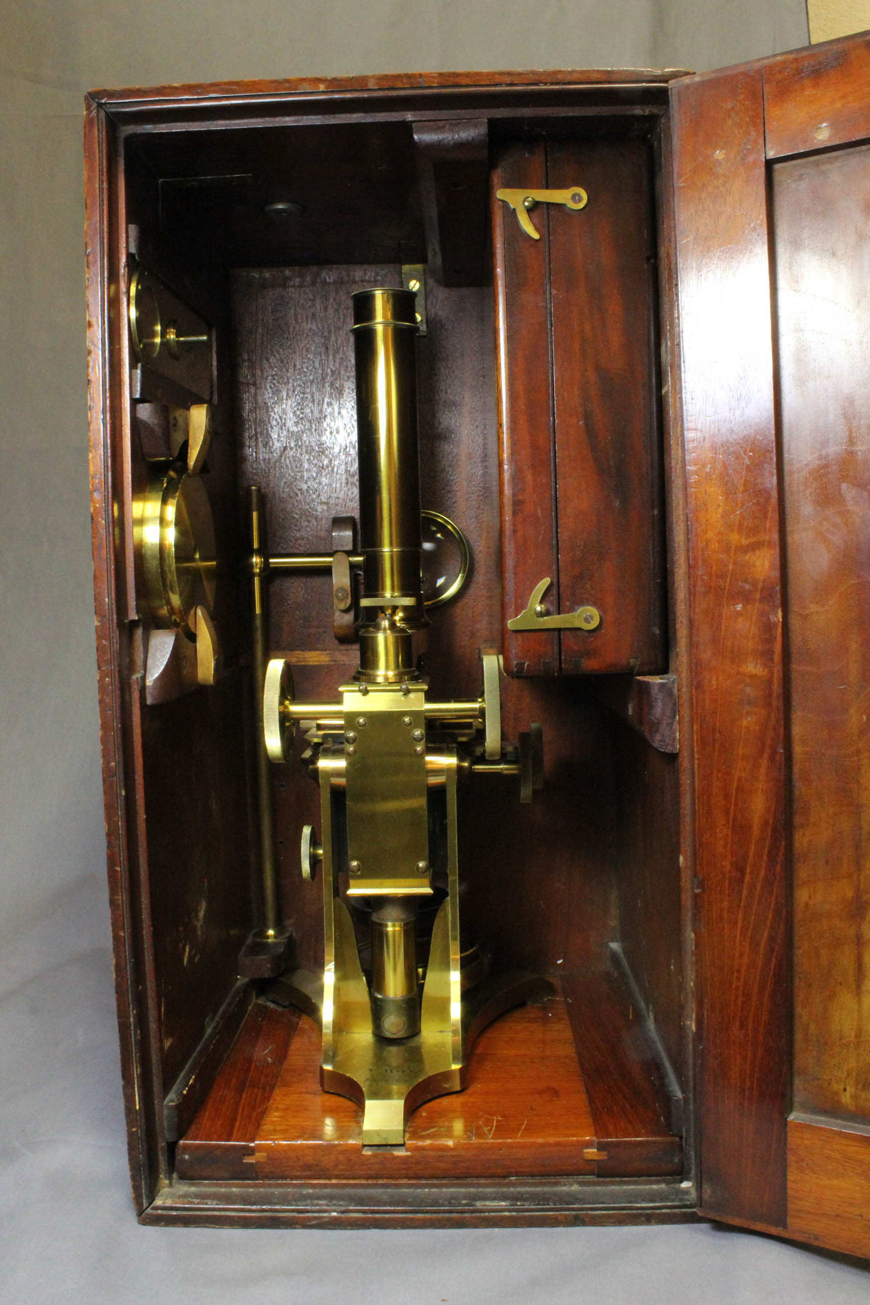
DESCRIPTION: This is a fine example of a monocular Ross Bar Limb microscope, made by the originator himself, Andrew Ross about 1847. It is unique in that it contains a comprehensive set of adapters for the substage to accept virtually all the different diameter accessories, by most makers of the time, and beyond. It arises from a 'splayed' Y-shaped foot on two thick flat uprights, each with an attached buttress at right angles to add stability. It is signed on the foot: 'A. Ross, London. No.324'
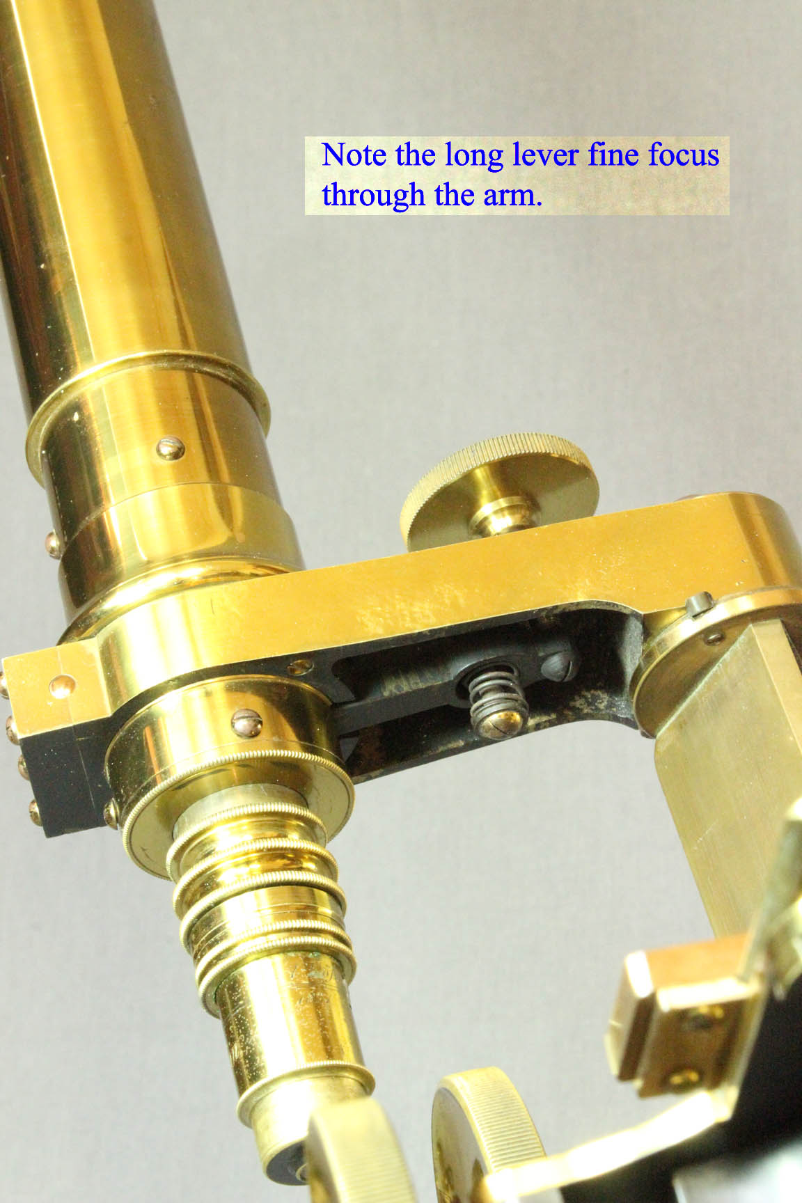
The limb, essentially a large box into which the 'bar' slides for coarse focusing by rack and pinion, is supported upon the uprights by trunnions. Protruding down from the bottom of the limb is a round tailpiece onto which the large (3 ¼ inches outside diameter) plane and concave mirror fits. The mirror is gimbaled and can slide up or down the tailpiece on a ring and can revolve fully on the tailpiece. The fine focus is the standard Ross long lever fine focus through the arm; the lever can be seen inside the arm when viewed from underneath it. The arm can rotate clockwise 90 degrees (rightward, as seen from the rear), for full access to the stage; there are stops at the normal and 90 degree positions. This feature of stops at the normal working position, and 90 degrees clockwise, are mentioned in Carpenter's first edition of The Microscope and its Revelations of 1856. These stops were not present in the earlier versions of Ross' Bar limb like No 161 also found on this site. The arm does not rotate to the left.
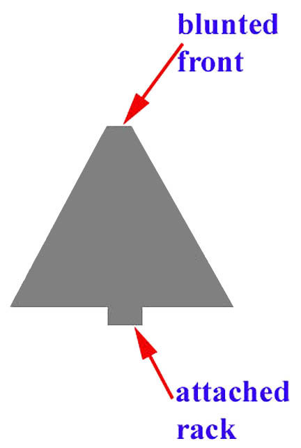 The bar on this microscope, as in all the earliest Ross Bar limbs, is nearly triangular in profile; the front apex of the the 'triangle' is flattened, creating what is technically an isosceles trapezoid with a very short base on that side. It is quite thick (about 1 ⅛ inches thick), compared to the smaller triangular bar in later second class microscopes made by Ross. The bar registers its four sides against the pinion box but not at the corners, as those areas where the corners of the bar would meet the pinion box are enlarged slightly to prevent the corners from being in contact with the pinion box.
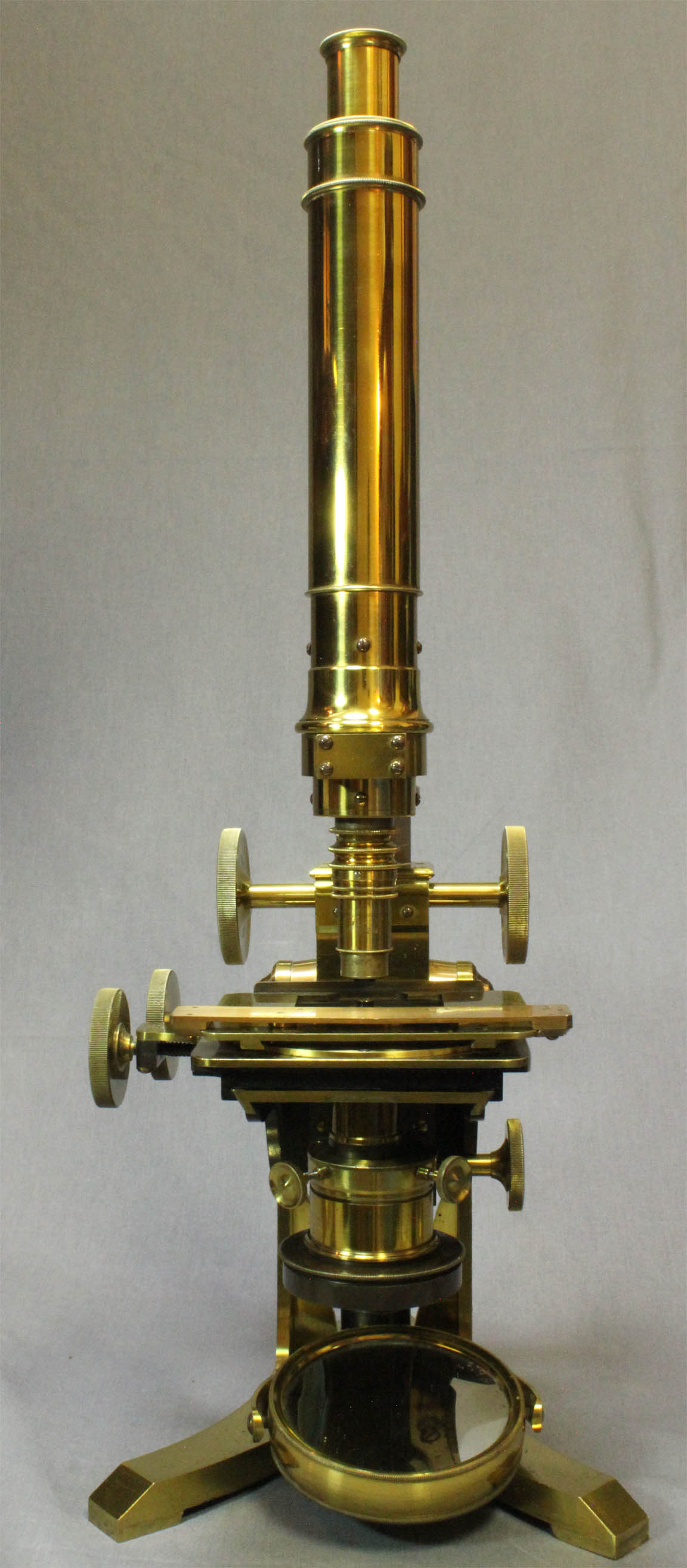
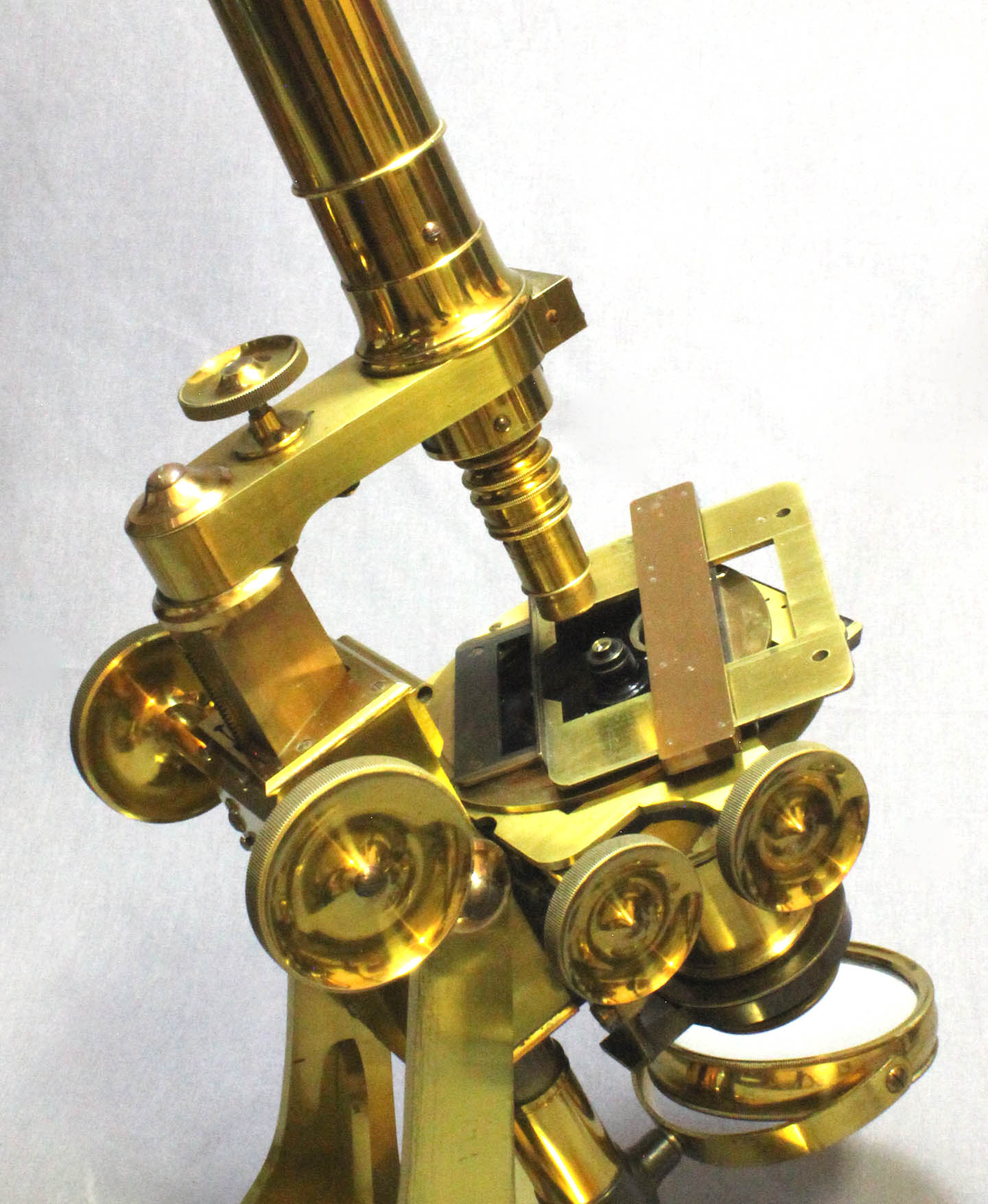 There is a mechanical stage controlled in the X and Y axes by knurled knobs. The square top plate of the stage can be manually rotated, and can slide back and forth. It has a fixed ledge at its rear and the slide is held between that fixed ledge and a bar that slides back and forth on the top plate. The sliding bar has a spring loaded pressure fitting at its center to grip the slide. The top stage plate has a hole on the right and also on the left to accept the stage fitting accessories such as the stage forceps, frog plate, etc.
 The substage has focusing by rack and pinion. Before the dedicated substage was popularized, most makers attached substage accessories to the underside of the stage. In the case of Ross Bar Limbs, and also Smith microscopes, this was accomplished by a dovetail under the stage and before that by
 fingers
on Ross Bar limbs. This substage dovetail facility is present on this microscope, perhaps suggesting the rack and pinion substage was a slightly later addition. The microscope comes in a hardwood case with a supplementary accessory case. The microscope and accessory box as well as the bench condenser, etc all fit the box well, but the height of the microscope is short for this case and so it may not have been original, though likely from the same era. The microscope fits into a sliding platform inside the bottom of the case. The main case has furniture to hold the frog plate, and the bench condenser and likely had other fittings that have been lost over the years. The accessory case fits inside the main case, and contains its full complement of accessories, some of which may not have been available at the time this microscope was made. Therefore, like many other Ross microscopes now known, at least some of the acccesories, and even the case, may be later additions. Two of the objectives are signed with dates in the 1850's, supporting the idea that this microscope was updated during that decade.
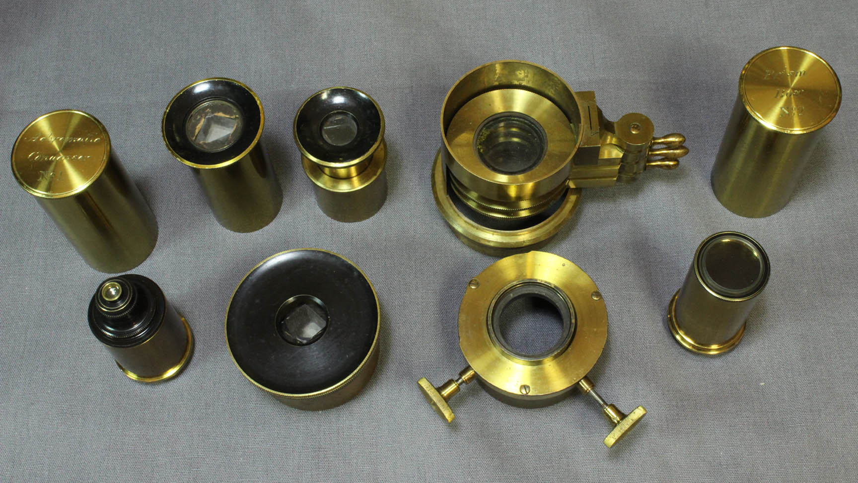
ACCESSORIES INCLUDE:
- Five objectives
- An adapter for the 1 ½ inch objective to allow it to fit on to the nosepiece
- Four eyepieces
- A Ross-type silver side reflector
- Stage bullseye condenser
- Two different size liveboxes
- Removeable centering apparatus for the substage
- A stacked rotating selenite fitting with three rotating selenites
- A large polarizer fitting into the bottom of the selenite fitting
- A wheel of apertures that slides into the dovetail under stage
- Three sleeves that screw into the substage ring which is itself controlled by rack and pinion
- An Achromatic condenser that threads into the centering apparatus
- Two dark ground condensers that also fit the centering apparatus
- A very large diameter dark ground condenser fitting into the larger diameter sleeve
- A Wenham-type Paraboloid dark field condenser
- A large frog plate(51.5 X 152 mm with a 33 mm glass window)
- A large freestanding bench Condenser
- Lieberkuhn fitting over the ½ inch objective
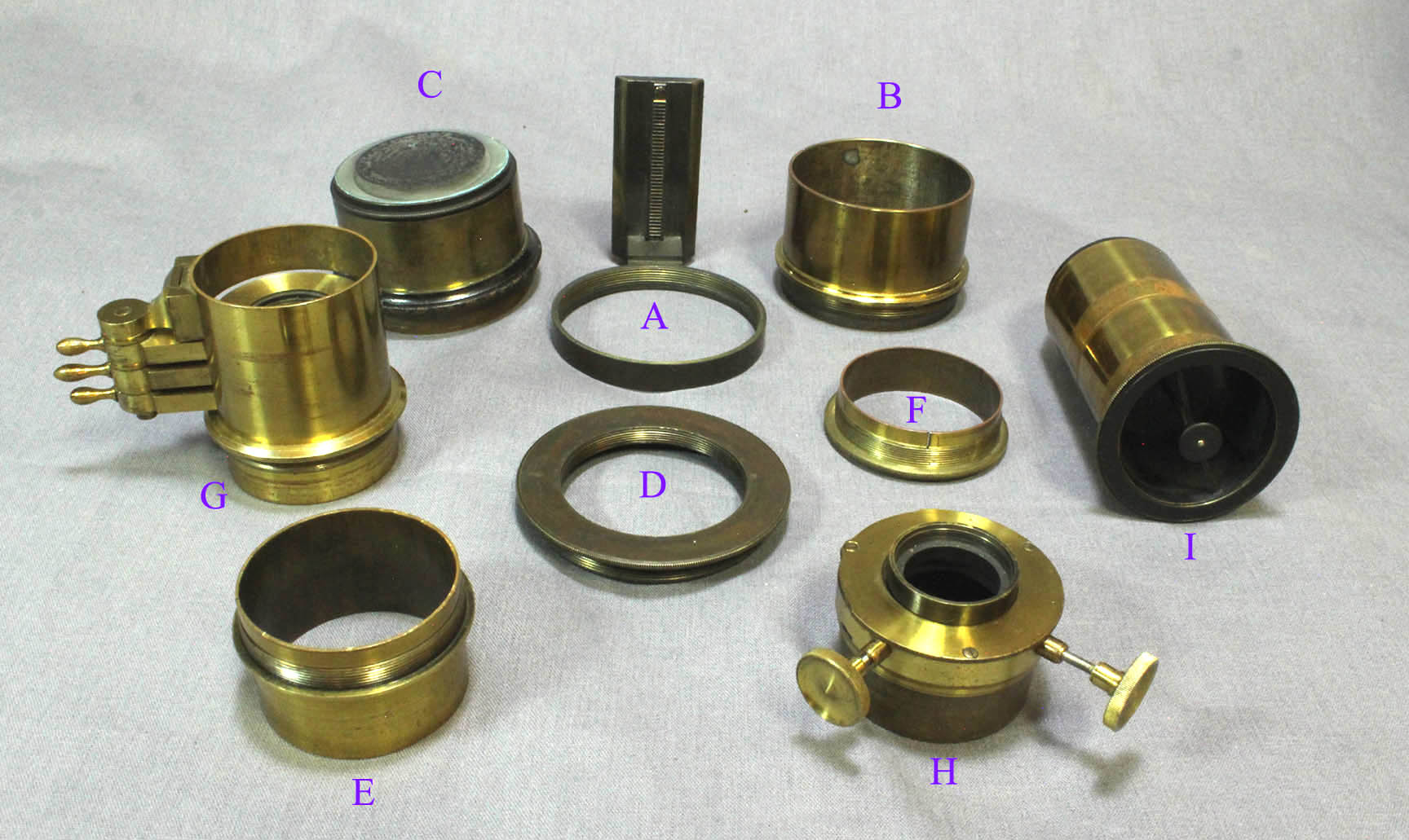
ADAPTATION OF THE ACCESSORIES TO THE SUBSTAGE:
 This is one of the most
 Universal
substages ever produced, in that it allows the installation of a broad variety of accessories of varying diameters. The substage ring(A) controlled by rack and pinion, is threaded. This large thread accepts the large threaded sleeve(B), into which the large dark ground condenser(C) slides. For all the other accessories here, the smaller diameter insert ring(D) screws into A. With this in place, the selenite assembly can screw in to D, or alternatively the short(F) or long(E) sleeves can screw into D. The centering apparatus(H), can slide into E or F or can slide into the top of the selenite assembly, (G). The paraboloid can be held by the sleeve F, at either its middle or its bottom end. The smaller sleeves have an inside diameter of about 40 mm, while the larger sleeve is about 51.5 mm inside. The shorter sleeve is used to allow the accessory being used to protrude through the bottom; the taller one allows the top of the accessory to reach the bottom of the slide. The taller small sleeve has a slit, but the other two do not. The centering device is threaded on top to accept the condensers. There are fittings in the accessory case to accomodate all of the above-mentioned accessories.
OBJECTIVES: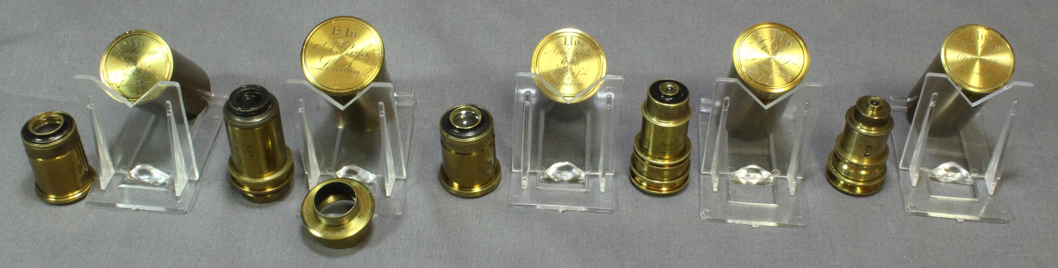
The five objectives include:
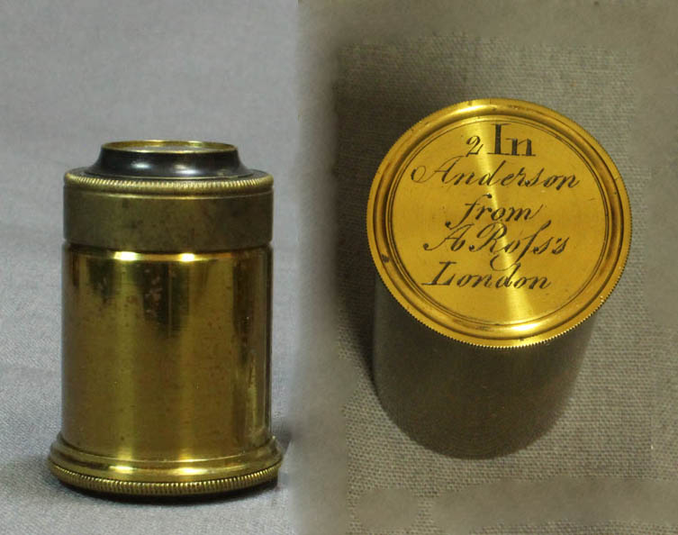
-A 2 inch objective in can signed on the lid: '2 In Anderson from A. Rofs's, London, with female thread screwing onto male thread on bottom of lid. Also signed on the bottom of the can: 2 In. The objective itself is unsigned. The tip of this objective can accept a Lieberkuhn, though the one which would fit it is lacking.
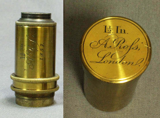
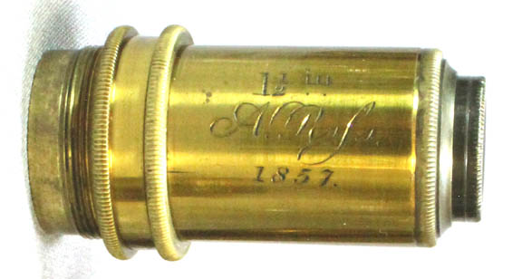
-A 1 ½ inch objective signed '1 12 In, A. Rofs, London, 1857, and on the can lid: '1 12 In, A. Rofs, London', and on the bottom of the can: '112'. This objective has a larger diameter thread than the nosepiece and so an adapter is provided to reduce the diameter to the smaller size of the female thread in the nosepiece; this requires removing the nosepiece adapter which is used for all the other objectives, since all the other objectives have female threads.
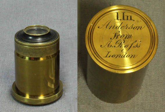
-A 1 inch objective in can signed on the lid: '1 In Anderson from A. Rofs's, London with female thread screwing onto male thread on bottom of lid. Also signed on the bottom of the can: 1 In. The objective itself is unsigned. This objective can accept a Lieberkuhn on its tip, though the Lieberkuhn which fits this objective is lacking.
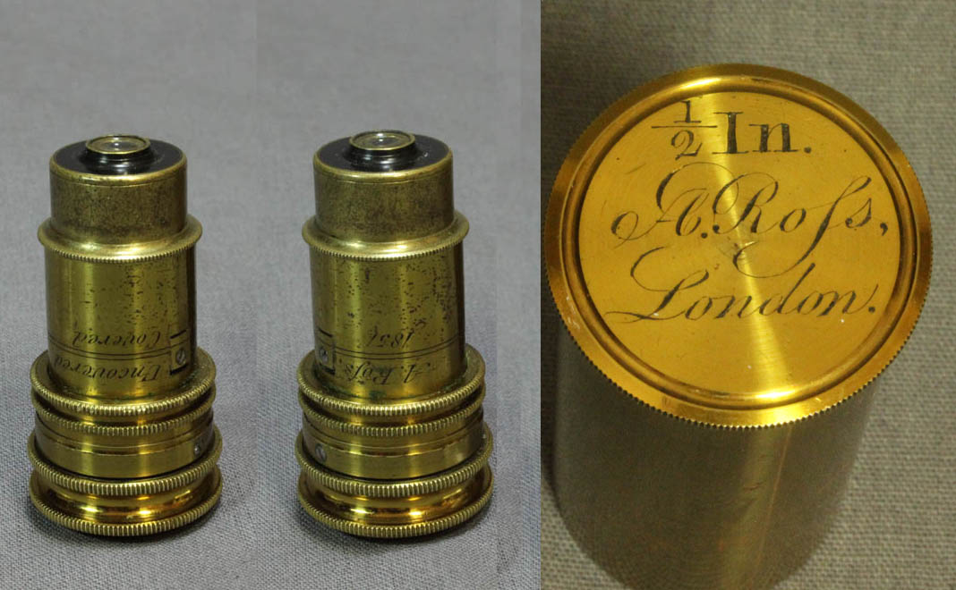
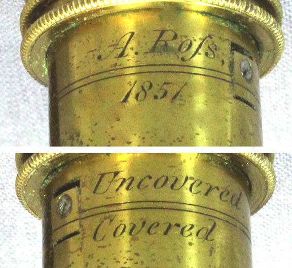
-A ½ inch objective with correction collar, signed: A. Rofs, 1851, and also signed '12 In, A. Rofs, London and also signed uncovered and covered above and below horizontal lines indicating the correct position for each setting. This objective has a female thread and screws on to the male thread on the lid of the can, the lid of the can signed on top: '12 In, A. Rofs, London' There is a silvered Lieberkuhn reflector present that fits this objective.
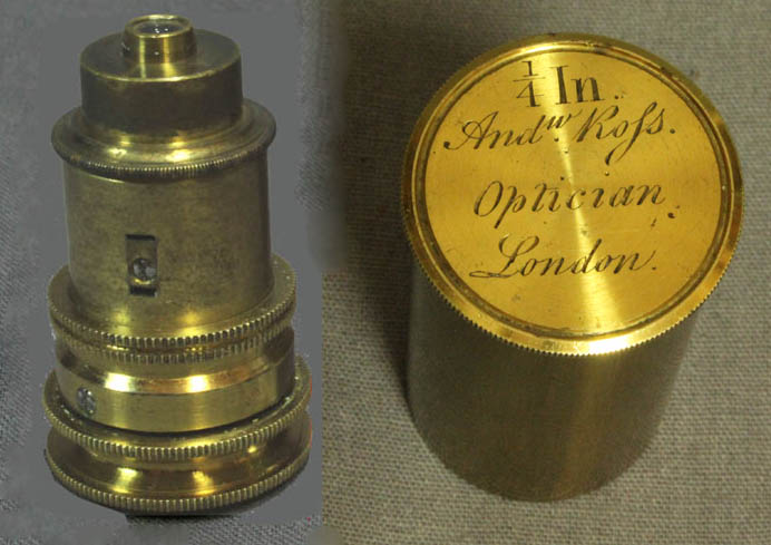
-A ¼ inch objective with correction collar, unsigned and without guidelines for setting the correction, with female thread and can signed: '14 In, Andw Rofs, Optician, London. The can is also signed on its bottom: '14 In. This objective also screws into the lid of the can. It can also accept a Lieberkuhn but this is lacking from this outfit.
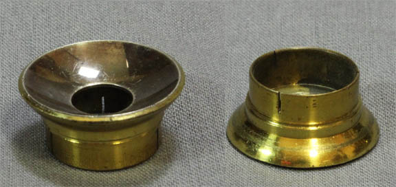
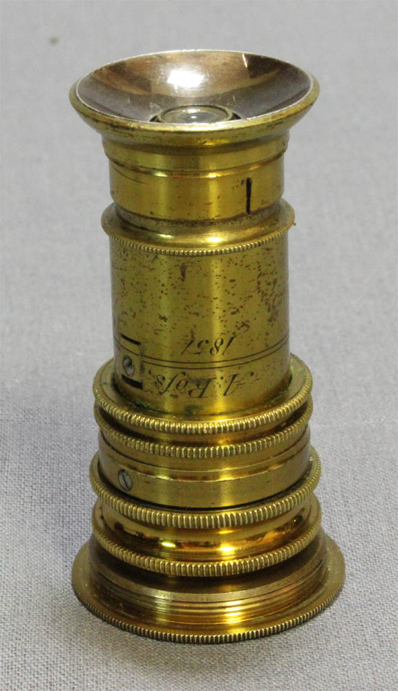
The ½ inch objective accepts a silvered Lieberkuhn reflector on its tip.
CONDENSERS:
There are four condensers designed for dark ground examination and one achromatic condenser for transmitted light.
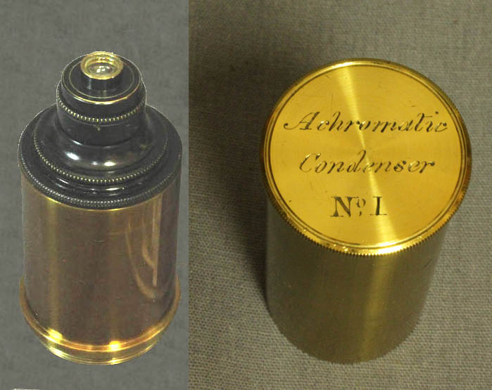
The achromatic condenser itself is unsigned but resides in a can signed: 'Achromatic, Condenser, No 1' on the top lid and simply '1' on the bottom of the can. It has a male thread which fits the centering device.
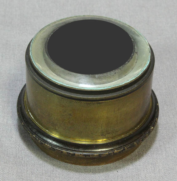
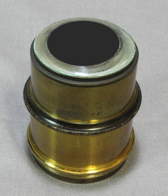
The lowest power and largest dark ground condenser fits into the largest sleeve adapter for the substage. It has an outside diameter of about 55 mm with the stop measuring about 36 mm in diameter while the lens has an outer diameter of about 45 mm. It is about 41 mm in total height and projects about 31 mm above its flange.
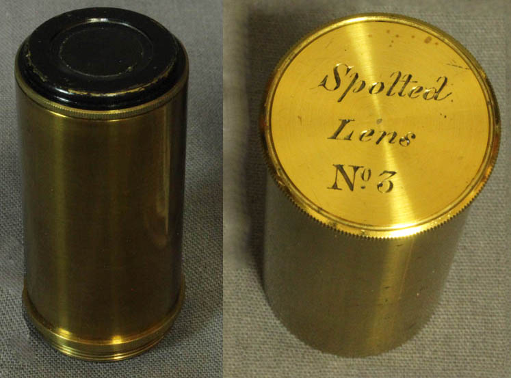
The No. 3 dark ground condenser is unsigned and resides in a can signed 'Spotted,Lens, No3 on the top and simply '3 on the bottom. It has a male thread which fits the substage centering device, and the lens stores by screwing into the lid of its can. The outer diameter is 22.5 mm while the visible lens is 13.5 mm with the stop about 11 mm in diameter. Excluding the thread it is 45 mm tall.
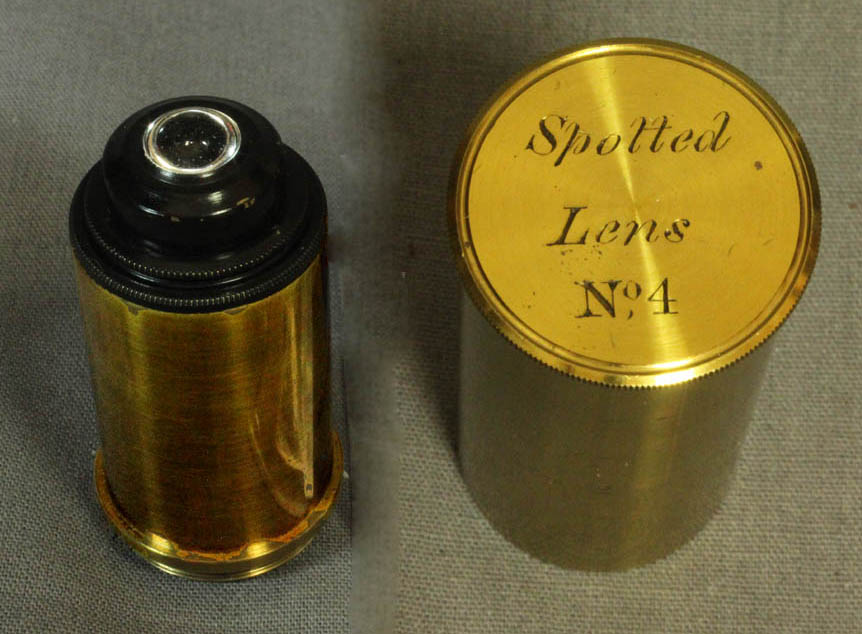
The No. 4 dark ground condenser is unsigned and resides in a can signed 'Spotted,Lens, No4 on the top and simply '4 on the bottom. It has a male thread, which fits the substage centering device, and it stores by screwing into the lid of the can. The outer diameter is 22.5 mm while the visible lens is 9 mm with the stop about 6 mm in diameter. Excluding the thread it is 45 mm tall.
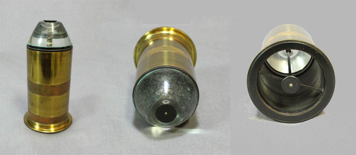
The paraboloid is also unsigned. It fits into the fitted wooden accessory case. It has a lacquered brass outside finish with slightly raised rings without lacquer at its middle and distal end which are 39 mm in diameter, compared to 38.5 mm for the lacquered portion. These rings serve as two different locations where the paraboloid can be held in the shortest small diameter sleeve. The stop is about 10.5 mm in diameter and its height in relation to the lens is adjustable by a screw controlled by a knurled knob at the bottom of the paraboloid.
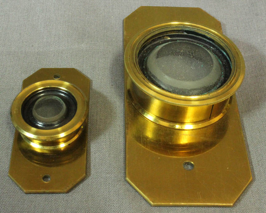
POLARIZATION APPARATUS
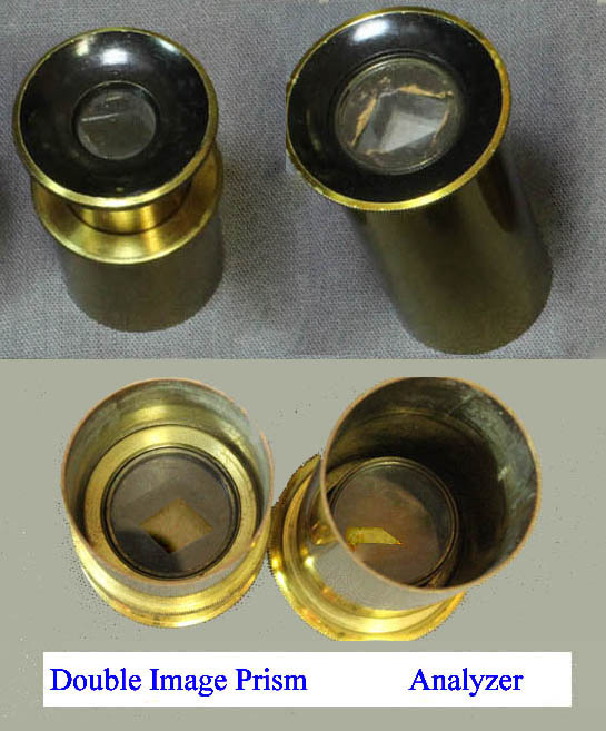 The microscope came with a reasonably complete set of Polarization apparatus. Among these is the 'prism box No. 2' in original can (right side of the image). It is interesting that a separate "prism box" which does screw into the centering apparatus, was supplied with these accessories, yet without any prisms. There are two eyepiece caps. One contains a traditional 'single image' Nicol prism analyzer. The other contains a 'double image prism' which is used to demonstrate the principal of double refraction of light rays which travel through the calcite. This is known as birefringence. Using ordinary substage illumination, viewing a single hole in an opaque slide, the 'double image prism' yields ordinary and extraordinary rays which appear as two dots of light. As the calcite cap is rotated, one dot appears to revolve around the other. When polarized light is used as the source of substage illumination, each of the dots alternately appear and disappear illustrating points of extinction. See the double image prism page for more information.
The substage apparatus containing the three stacked rotatable selenites(retarders), has little levers so each of the three selenites can be swung in or out of the optical axis at will. Each rotating selenite, is marked with 'P | A' for the direction of the positive axis. They are also each labeled with a fraction that presumably indicates their degree of retardation. These labels are all on the inner selenite rings which ride inside the outer lacquered brass rings; this makes the retardation labels very hard to read, as they are partially obscured by the outer brass rings*. But they do appear to be the standard 9/4, 3/4, and1/4λ. The entire set of selenites slides on and off of the brass support by a small dovetail**. This is required, as the levers for the selenites protrude preventing turning of the housing required for its installation into the substage ring. The support of the stacked selenite apparatus is threaded near its lower end to screw into the shorter smaller diameter fitting for the substage ring controlled by the rack and pinion. When installed, it allows its bottom to protrude and accept the large polarizer which slides into its bottom; the top accepts the centering device, thus allowing the use of a condenser with the polarization apparatus. The purpose of using a condenser with this apparatus is to intensify the image especially when using high power. The stacking selenite apparatus, listed as being 'in an improved setting' in 1872, was not listed in the 1862 or earlier Ross catalogs, illustrating that it was likely an accessory that was added later than the time this microscope was originally constructed. For more about the selenites, please see the selenites page. For more about the interesting experiments the double prism can be used for, see the double image prism page.The author would like to thank Dr. Joe Zeligs for the catalog information.
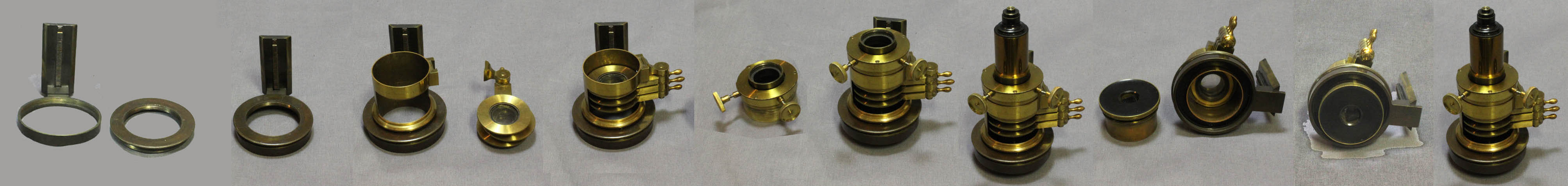
Below is an image to illustrate the assembly steps for the substage polarization apparatus. The substage is threaded to accept the insert of smaller diameter threads. The first image shows the substage ring and the insert. The second image shows the insert screwed in. Once this is installed, the housing for the selenites can be screwed on to it. The selenites themselves, attached to that housing by a dovetail, must be removed until the housing has been screwed on because the housing would not be able to fully rotate with the selenites installed. The next images show how the centering apparatus slides into the top of the selenite housing. The achromatic objective can then be screwed on to the top of the centering apparatus to be used as a condenser. Finally, the polarizer is pushed into the selenite housing from the bottom as its black and knurled rotating side is of larger diameter than the threaded insert.
 Interestingly, an extremely similar substage polarizing apparatus to that included with this microscope, including centering apparatus, polarizer, and stack of selenites, topped off with an achromatic condenser, is pictured in Richard Beck's book of 1865 entitled Treatise on the Construction, Proper Use and Capabilities of Smith, Beck and Beck's Achromatic microscopes. To this author, this suggests that at least in the beginning, one manufactory was making this apparatus for both firms. As time went on, the design of this apparatus was changed to suit the newer design of the Ross substage condenser arrangement. In the later versions the centering apparatus was now integrated so that all accessories fit into it. In these versions, the stacked selenite apparatus simply had a thread on top to accept a condenser, as the entire assembly could then be centered at once. The thread on the top of the newer stack of selenites is the RMS standard for objectives(which were often used as condensers), not the thread found with this early Ross instrument. The condensers found with this microscope will not fit the top of the newer versions of the stack of selenites. Conversely, accessories from other makers were sometimes made in sizes to fit Ross (and other) microscopes. Examples include a large version of the Powell and Lealand
 High Power Achromatic Condenser
and a larger than usual version of Powell and Lealand's polarizer, selenite stack and condenser. 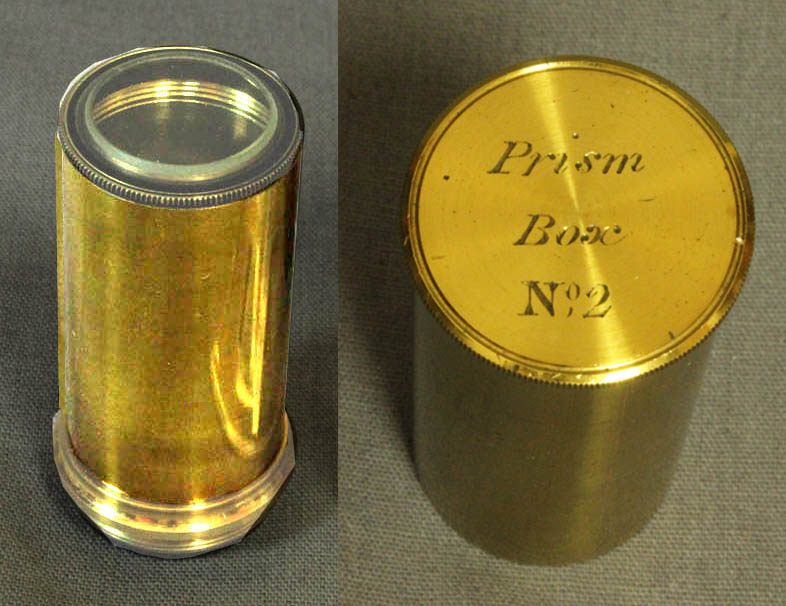
An uncommonly seen accessory found with this microscope is the empty 'Prism Box No. 2'. This is a housing, supplied in its original can, that is designed to accept a Nicol or other type of prism such as the double image prism. The user could equip it in whichever way he saw fit. This one remains empty.
*This is in contrast to the later versions of this apparatus where the labels are on the outside rings, much easier to read.
**This selenite arrangement differs from the later version of the stacked selenites. In the later version, the selenite group is no longer attached to the housing by a dovetail, but rather screwed on. That arrangement would not have worked with the microscope substage shown here because the housing has to screw on to the substage which cannot be done with the selenites in place; the later version simply slid into the larger diameter opening of the later centering apparatus
***In addition, the later version simply slides into a larger centering substage, and has a thread for a condenser directly on its top. While the early versions are unsigned, the later versions are signed 'Ross London' with a number.
EYEPIECES:
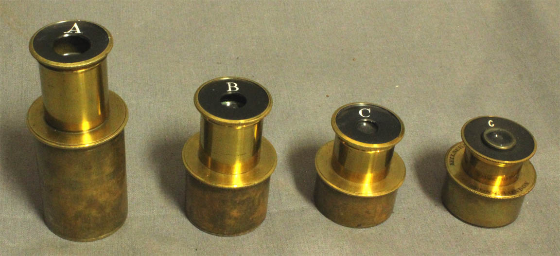
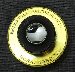 Four eyepieces accompany the instrument. These include one each signed 'A' and 'B' and two 'C'. The latter includes one with no other writing on it and the other C eyepiece is signed: 'Kellner's Orthoscopic, Ross, London' Note the orthoscopic# has a smaller and more modern letter "C" than the other three eyepieces.
There are spaces in the fitted accessory case for the three shorter eyepieces, but the longer 'A' eyepiece is meant to store in the optical tube when the microscope is in its case. The caps of these eyepieces may be removed in order to substitute the analyzer eyecap or the double image prism eyecap.
Four eyepieces accompany the instrument. These include one each signed 'A' and 'B' and two 'C'. The latter includes one with no other writing on it and the other C eyepiece is signed: 'Kellner's Orthoscopic, Ross, London' Note the orthoscopic# has a smaller and more modern letter "C" than the other three eyepieces.
There are spaces in the fitted accessory case for the three shorter eyepieces, but the longer 'A' eyepiece is meant to store in the optical tube when the microscope is in its case. The caps of these eyepieces may be removed in order to substitute the analyzer eyecap or the double image prism eyecap.
# The use of the word 'orthoscopic' in this case is not the modern usage. In reality, Kellner invented an achromatic eyepiece. It was not orthoscopic in the modern sense as optical defects other than chromatic aberration are not corrected in the Kellner eyepiece as they are in the modern orthscopic eyepiece. Kellner invented his achromatic 'orthoscopic' eyepiece around 1849 and died in 1855. Ernst Abbe invented the modern orthoscopic eyepiece in 1880.
ACCESSORIES FOR THE STAGE:
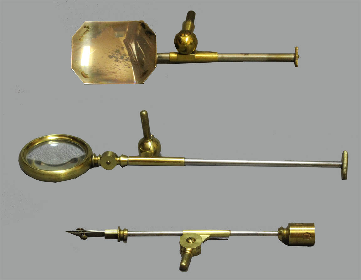
Accessories attaching to the stage include the Ross-type silvered side reflector, the stage forceps, and the stage bullseye condenser. All these are used for studying opaque objects. They all attach by pin to holes on the right or left side of the stage. They do not fit the holes on the side of the limb, also designed to hold similar accessories.
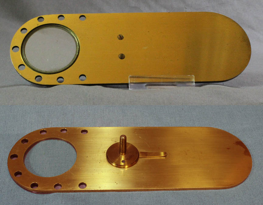
The frogplate attaches to the same holes in the stage as the stage forceps etc.
Also included are two Varley-type live boxes(with channels around the bottom glass).
BENCH CONDENSER:
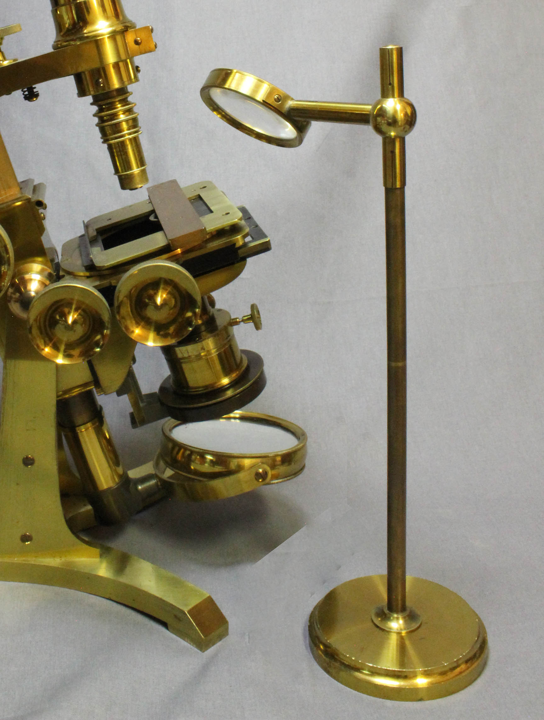 A large bench(stand-alone) condenser, is also supplied. It is stored in the main case.
UNDERSTAGE WHEEL OF APERTURES:
 Preserved with this microscope is the understage wheel of apertures that slides into the dovetail on the bottom of the stage. This would be used with the mirror without a condenser to regulate the size of the cone of light. One aperture of this wheel has a slightly tinted glass filter over the opening.
HISTORY OF THE ROSS BAR LIMB MICROSCOPES:
Two famous firms reported Bar Limb microscopes in 1843, namely Hugh Powell and Andrew Ross. Some would give Ross priority due to the fact he said he claimed he had made many before that date, but Powell's description was published one month earlier in the year, thus leading some to credit him.
In any case, Andrew Ross, the more prolific of the two, first constructed microscopes for the trade, and his initial microscopes are likely signed by others. The first microscope clearly known to be of his make was the simple and compound microscope he made for Valentine in 1831 and it was reported in the Transactions of the Society of Arts of 1832. Ross went on to make his Lister Limb microscopes of various designs until 1843 when he first came up with his famous microscope with a Bar Limb and Splayed foot, supporting the limb between two uprights. This design, along with its accessories, was first reported in the London Physiological Journal of 1843, and continued to be Ross' standard design until his death in 1859. Following that, the design was continued by his son Thomas, who added improvements, such as the Wenham Binocular tube (1860), as they became available. The signature on the microscope on this page is that used by Andrew Ross between the years 1847 and 1859. Serial numbers from that period range between about No. 230 and No. 1857 or higher. Therefore, one can conclude that serial number 324 is from about 1847.
As noted above, the accessory case is likely a later addition, and contains some apparatus that is actually dated later, and other things, such as the stacked selenite fitting for the substage, that apparently were not available, or at least not listed in the Ross catalogs, at the time this microscope was originally made.
SUBSTAGE ARRANGEMENT:
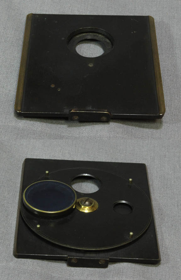
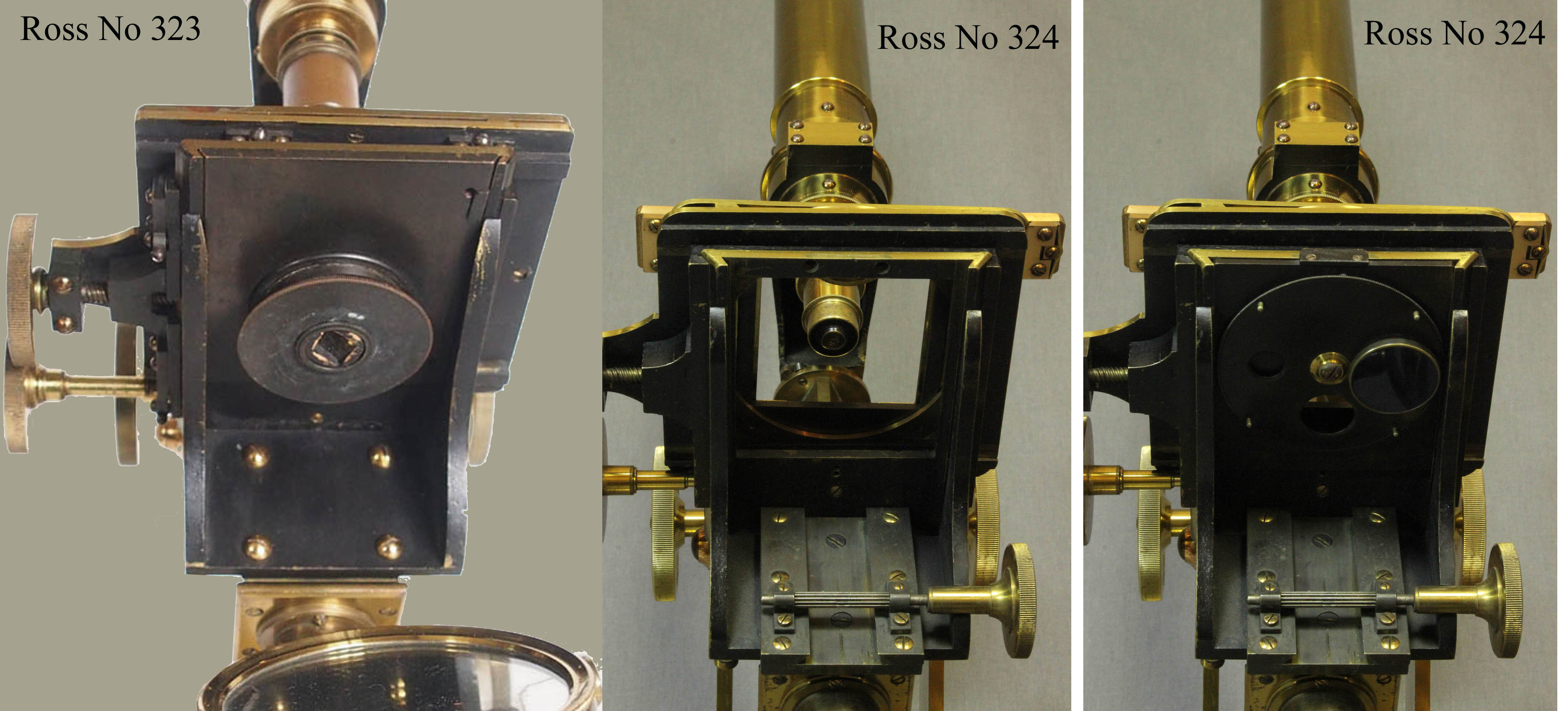 A word about the substage arrangements of the Ross Bar Limbs is in order. As can be seen in the images to the left, starting with an image of the Ross Bar Limb No 323, at first the substage apparatus attached via a sliding dovetail on the bottom of the stage, but sometime, perhaps in the 1840's Ross started to supply rack and pinion substages. As seen in the next two images, of Ross No 324, the microscope featured on this page, the rack and pinion was added despite the persistance of the dovetail fitting under the stage. There is an advantage though to leaving the dovetail there and that is the ability to use the wheel of stops that slides into it to regulate the size of the cone of light passing through the specimen when the mirror is used without a condenser. Later on, this feature, a ring of apertures to regulate the diameter of the illuminating light source, was built-in to some condensers. This is needed to create optimal illumination, because the top element of the condenser needs to be close to the slide and the aperture in this case must be built in to the condenser below some of the optical elements*. Since the dovetail arrangement remains on the vast majority of Ross microscopes until the rack and pinion substage became more common, perhaps in the late 1840's, it may be that the rack and pinion arrangement here was part of a later upgrade just like the some of the accessories, which are likely also later. Judging from the image of Ross No 323, it would appear that it would be quite straightforward to add the rack and pinion to the substage as originally configured. Rack and pinion substages are found in most(but not all) examples of Ross' first class bar limb microscopes dating from about 1850.
It is interesting to note that another signed Andrew Ross bar-limb microscope of smaller size has the same serial number (324). This microscope hasthe exact same signature as the No 324 documented on this web page. The author and Joe Zeligs are unaware of any other duplicated Ross serial numbers. This may simply have resulted from a simple mistake while Ross was making these microscopes, either by clerical error or an error by the engraver.
*Later on, it was also discovered that adjusting the lightsource so that it was imaged in focus on the condenser aperture provided optimal illumination improving resolution. This became part of the illumination technique known as Kohler illumination.
This microscope sold for $3660 (in 2019 dollars) in 1985 at a Phillips auction. It was in its current configuration and had the current accessory case with it at the time.
The author is very grateful to Dr Joseph Zeligs for his careful proofreading of this page, and helpful suggestions and for supplying catalog information as well as additional reference materials.