No. 1
| DESCRIPTION | HISTORY | CONDITION |
Please Click On Any Picture for a Larger Version
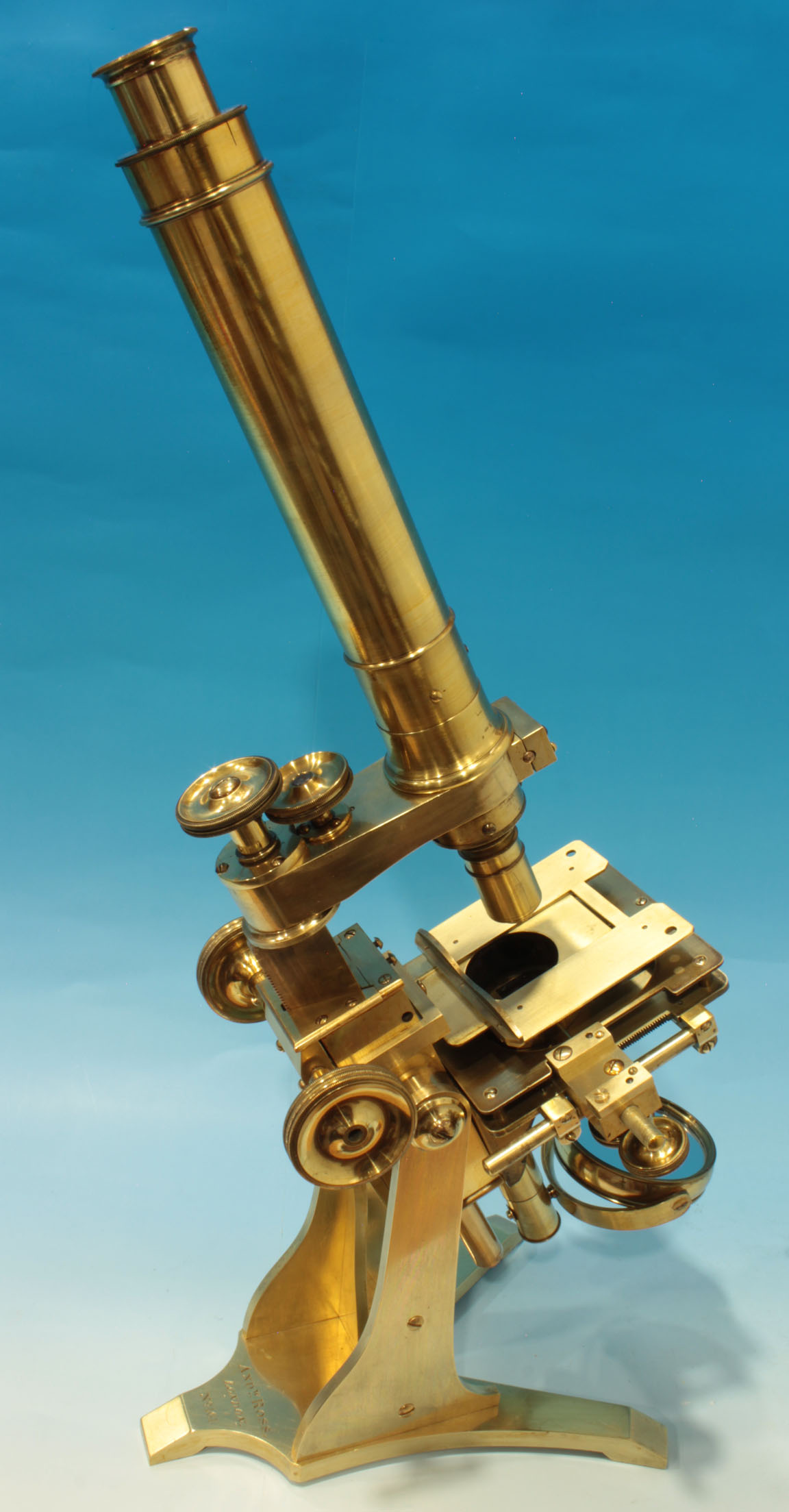
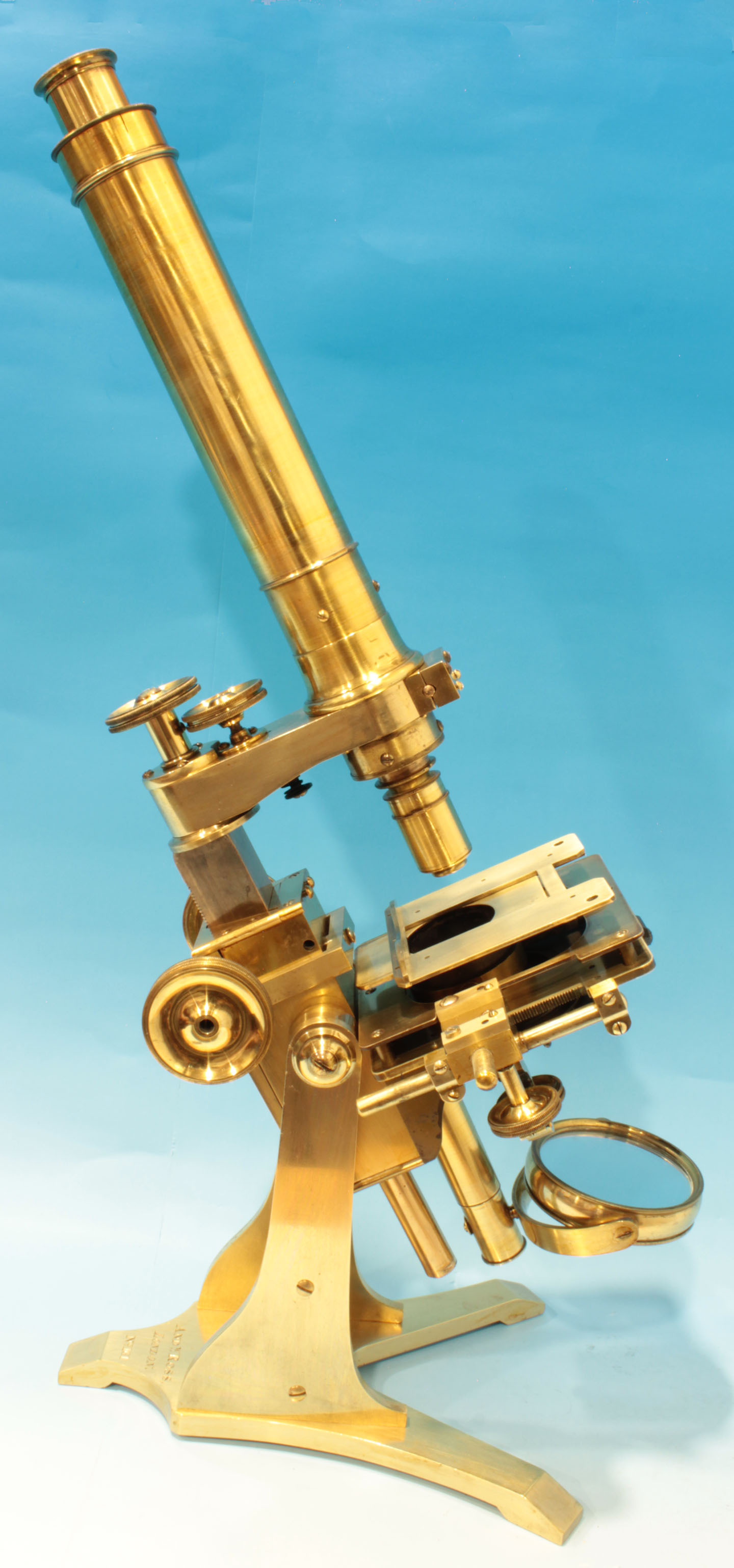
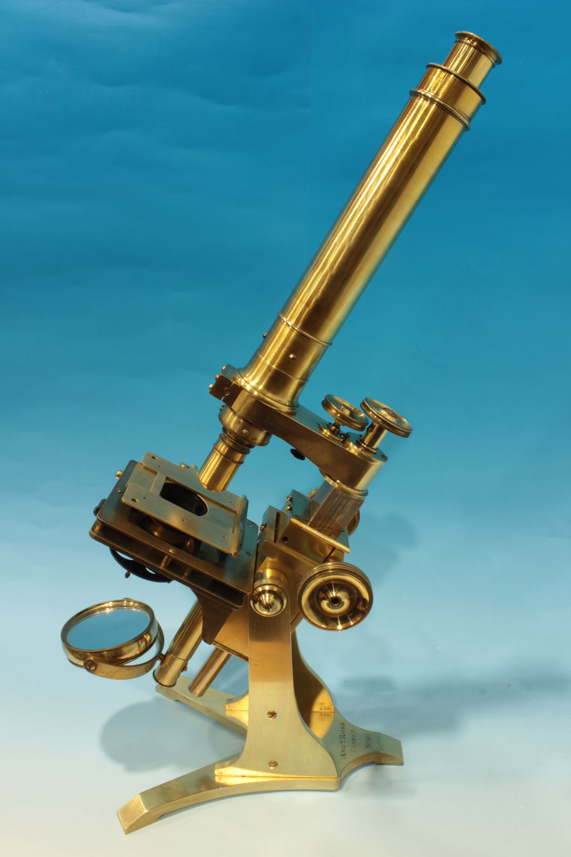
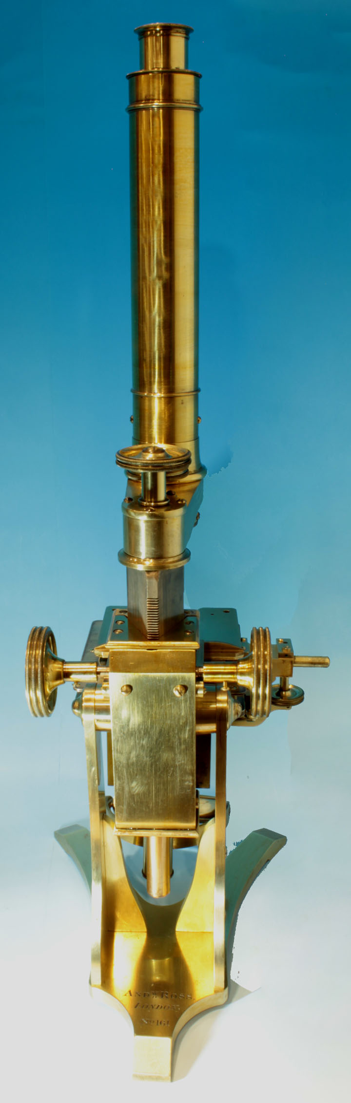
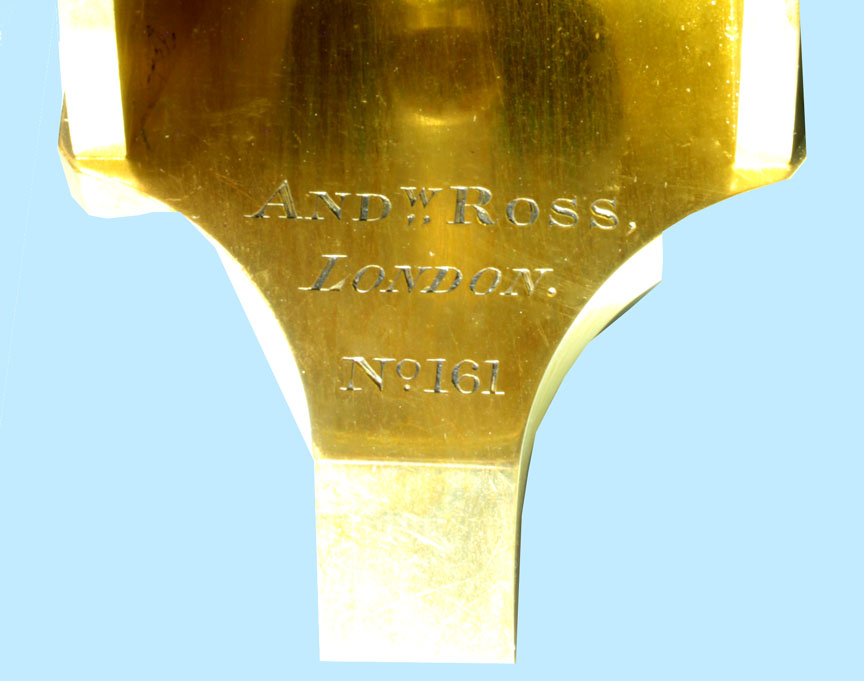
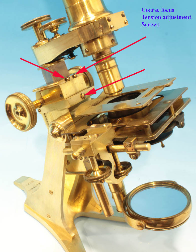
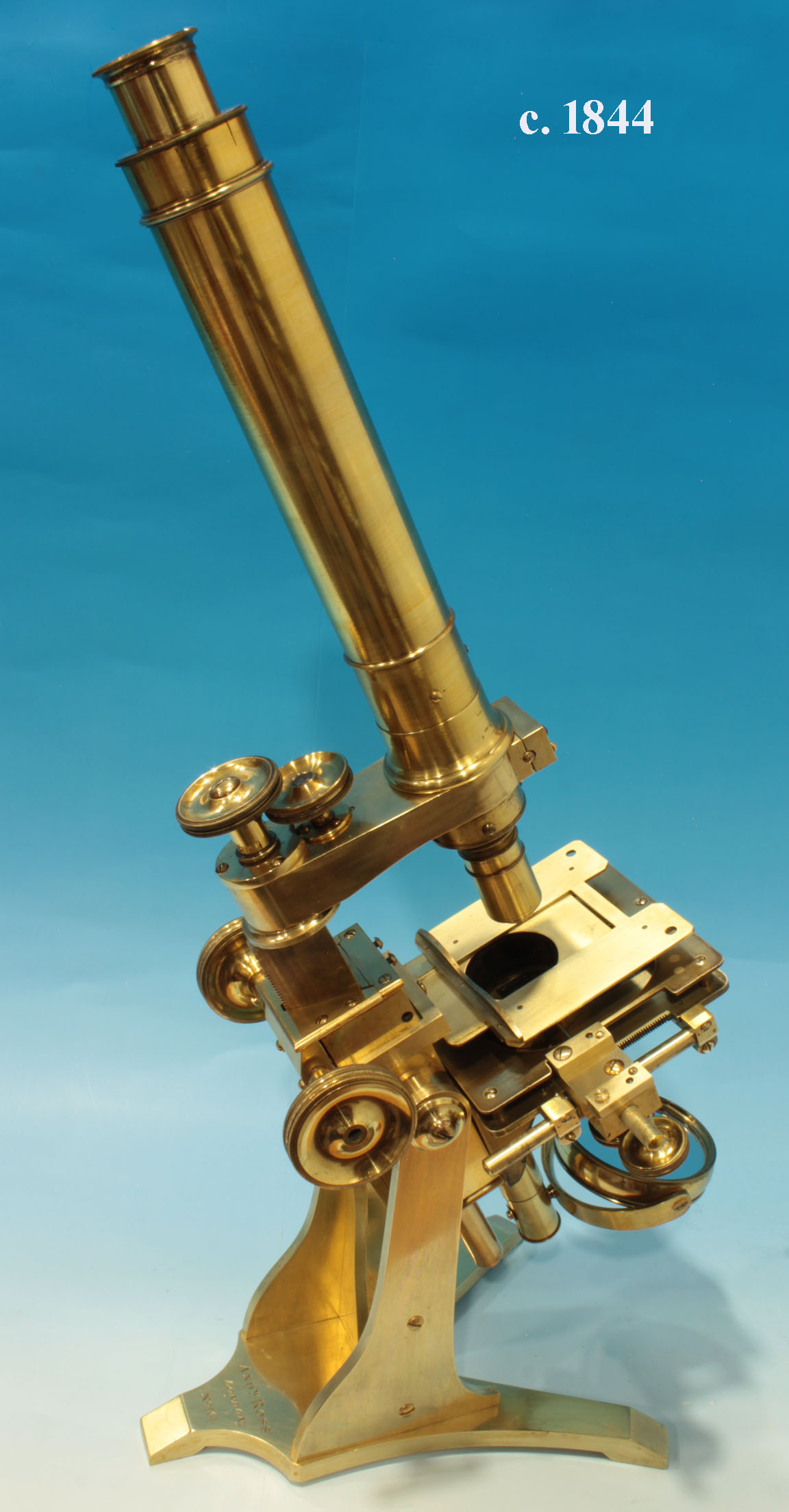
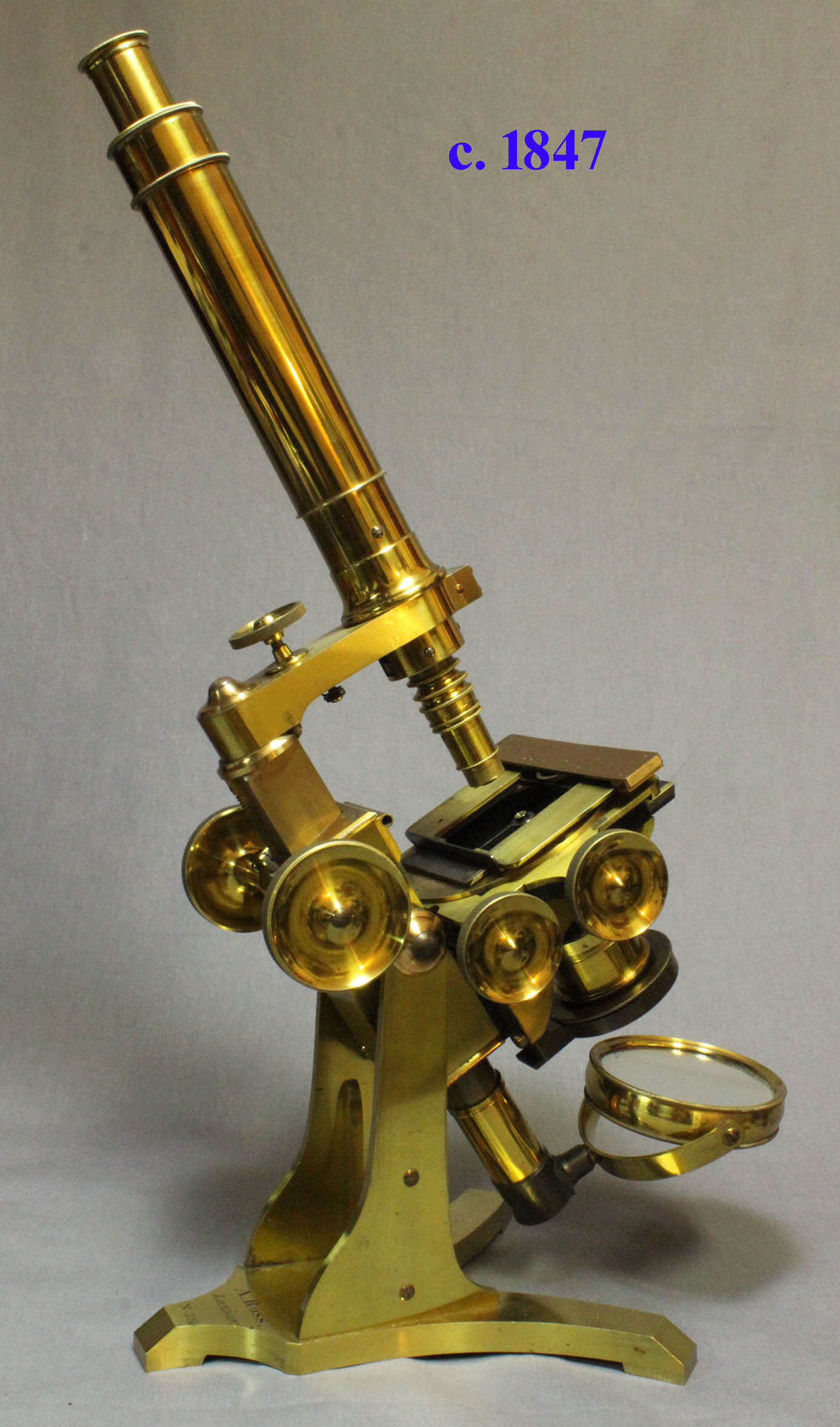
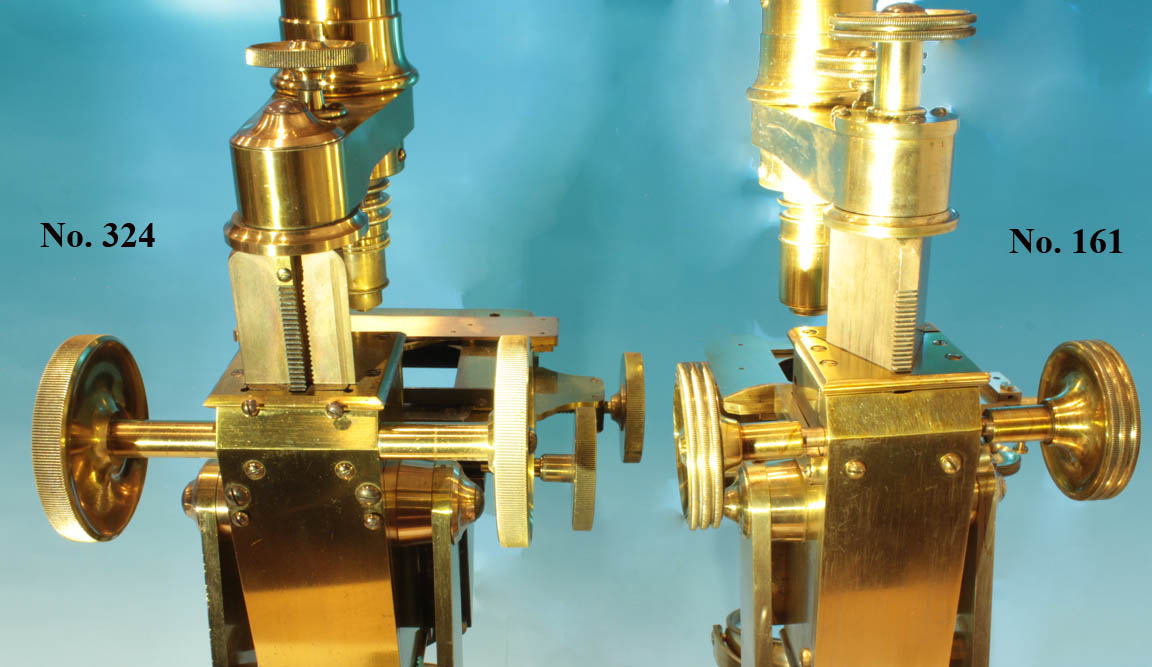
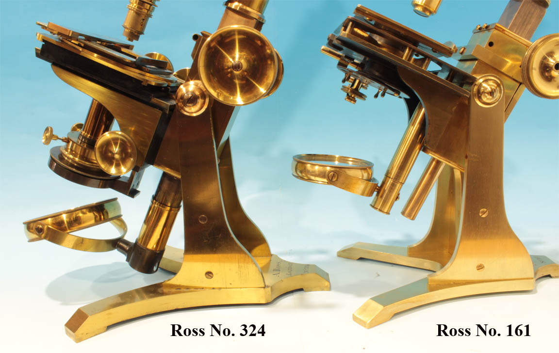
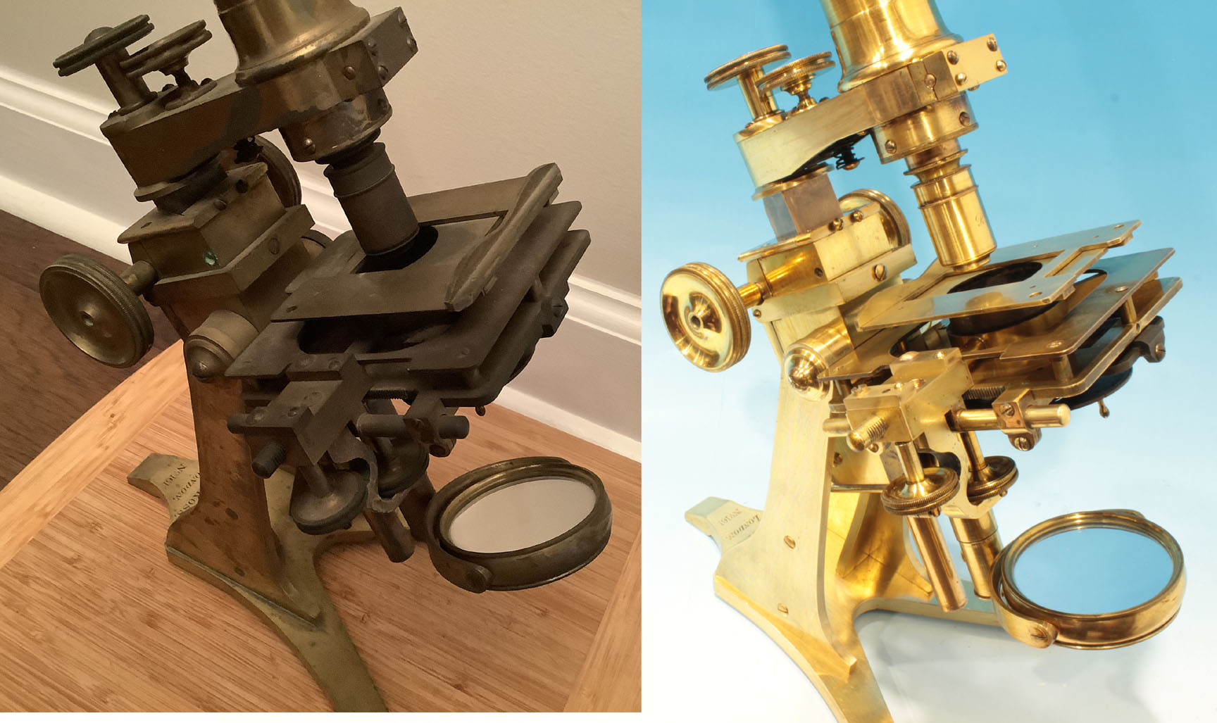
AndW Ross, London, No. 161(This signature dates the microscope to after 1841, but before 1847; (see history below). Flat uprights with inward buttresses arise from the foot to support the microscope. These uprights are attached by joints on each side of the pinion box/limb housing box. The tension on these joints can be adjusted by the screws, and with the correct amount of tension, the microscope will be securely positioned to any angle of inclination from vertical to horizontal. The stage has about a one inch travel in both the X and Y directions controlled by the two horizontal knobs under the right-hand side of the stage. The top plate of the stage has a hole on the right and on the left to accept stage-mounted forceps or other accessories. The coarse focus is by straight rack and pinion acting on the apex of the trapezoidal bar which has a rack machined into it. The top half of the bar has a isosceles trapezoid shape in cross section; a long section at the bottom of the bar has been machined to a round shape, projecting through a hole at the bottom of the gear box/limb housing, and can be seen to move up and down as the limb is focused by the coarse focusing knob. The tension on the trapezoidal portion of this bar can be adjusted by three screws on the front of the pinion box/limb housing(right). The larger screw in the middle acts on a heavy brass leaf spring inside which presses against the wide flat surface of the bar. The other two screws adjust the tension of two contact points at the top of the pinion box. These screws allow adjustment for wear and when properly adjusted, just the right amount of tension on the bar to prevent it from falling under the weight of the arm and tube is easily achieved. Fine focus is controlled by a knurled knob on top of the limb acting on a long lever. One revolution of this knob moves the objective 1/500th of an inch. The nosepiece is sprung thus reducing the chance of damaging the the glass or object under observation. Another taller knob holds the arm in place, tension inside imparted by a coiled spring. When loosened, the arm may be rotated away from the stage in either direction. The arm may be completely removed if desired; in the 1840s, another arm for single lenses could be substituted.
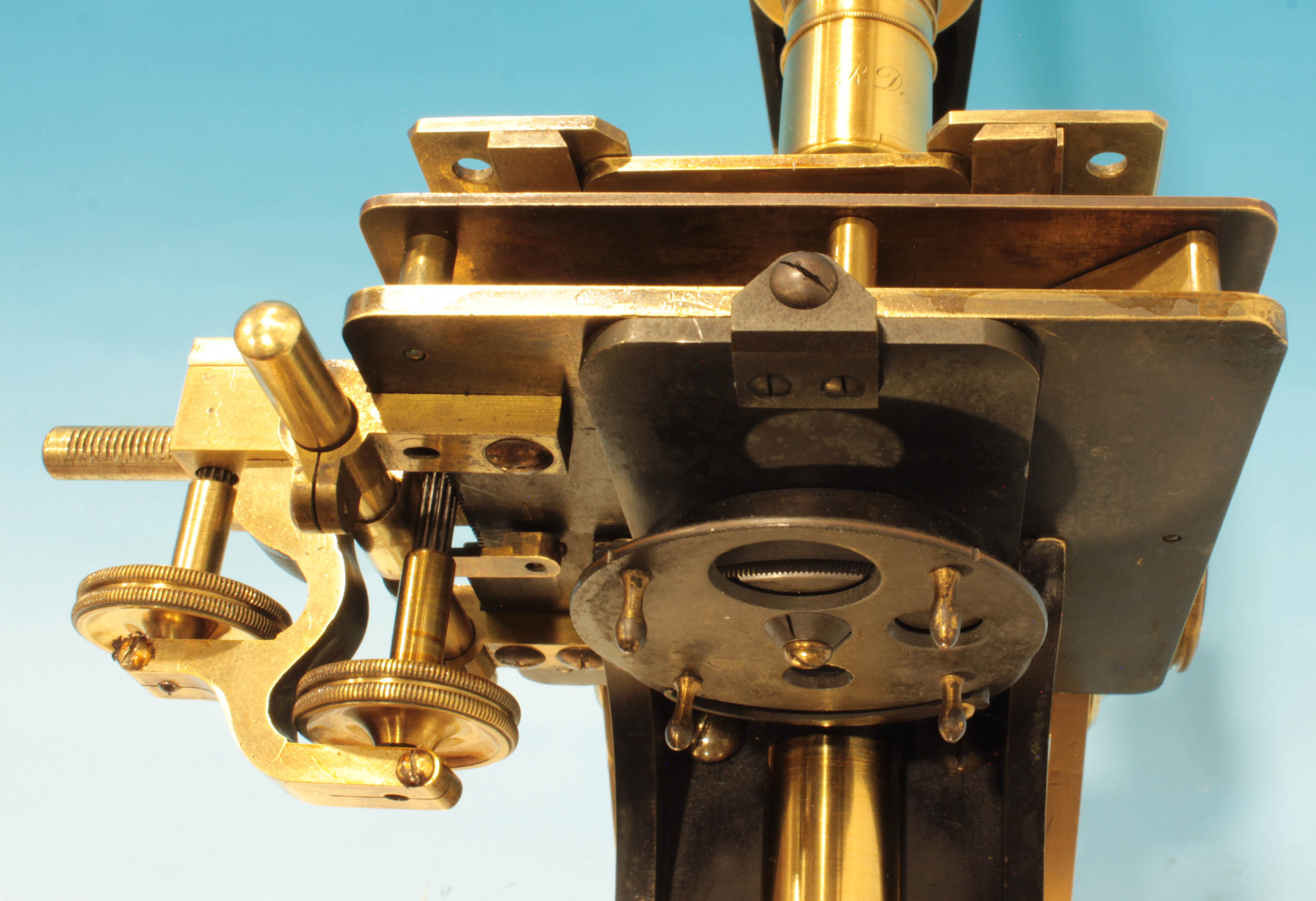
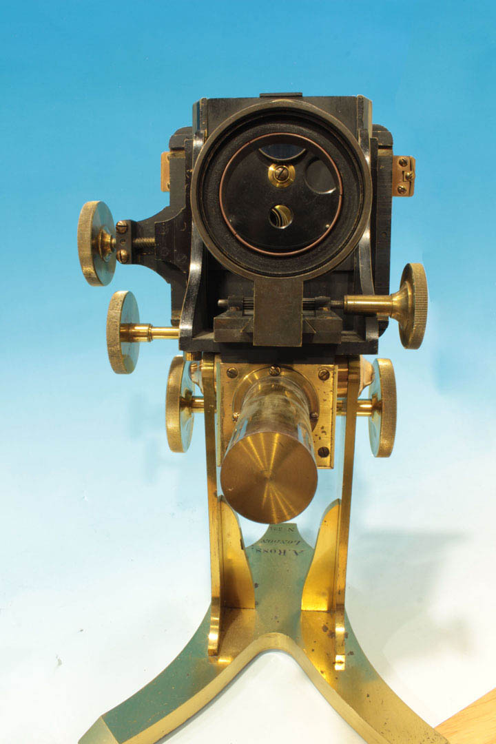
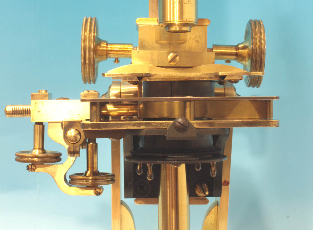
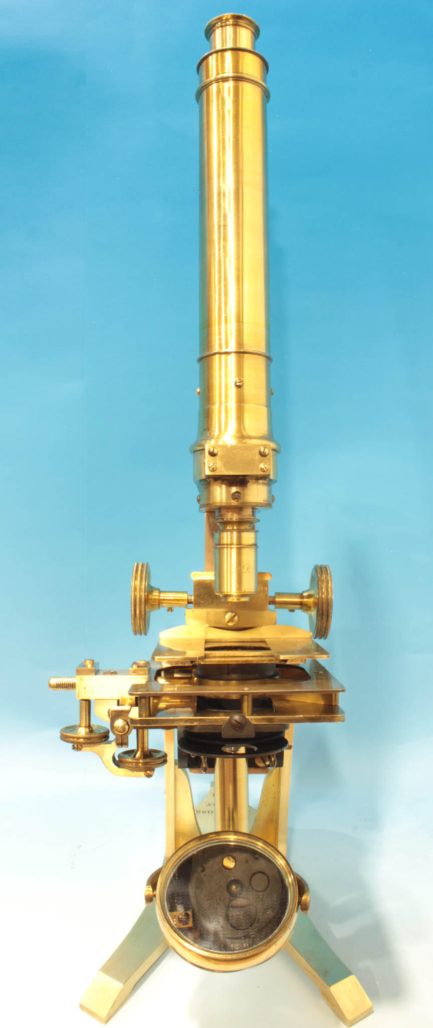
 The mechanical stage is supported on an L-shaped bracket screwed onto the front of the pinion box/limb housing. The tailpiece holding the gimbaled mirror is screwed in to the bracket. The mirror support is screwed into the tailpiece at a fixed distance from the stage. The controls for the mechanical stage project below the stage and are situated next to each other, as seen from the front of the microscope. The knob further away from the stage acts on a rod which has a rack cut into it and controls movement in the X-axis. The pinion of the knob closer to the stage acts on a rack cut into the bottom plate of the stage to move the stage in the Y-axis.
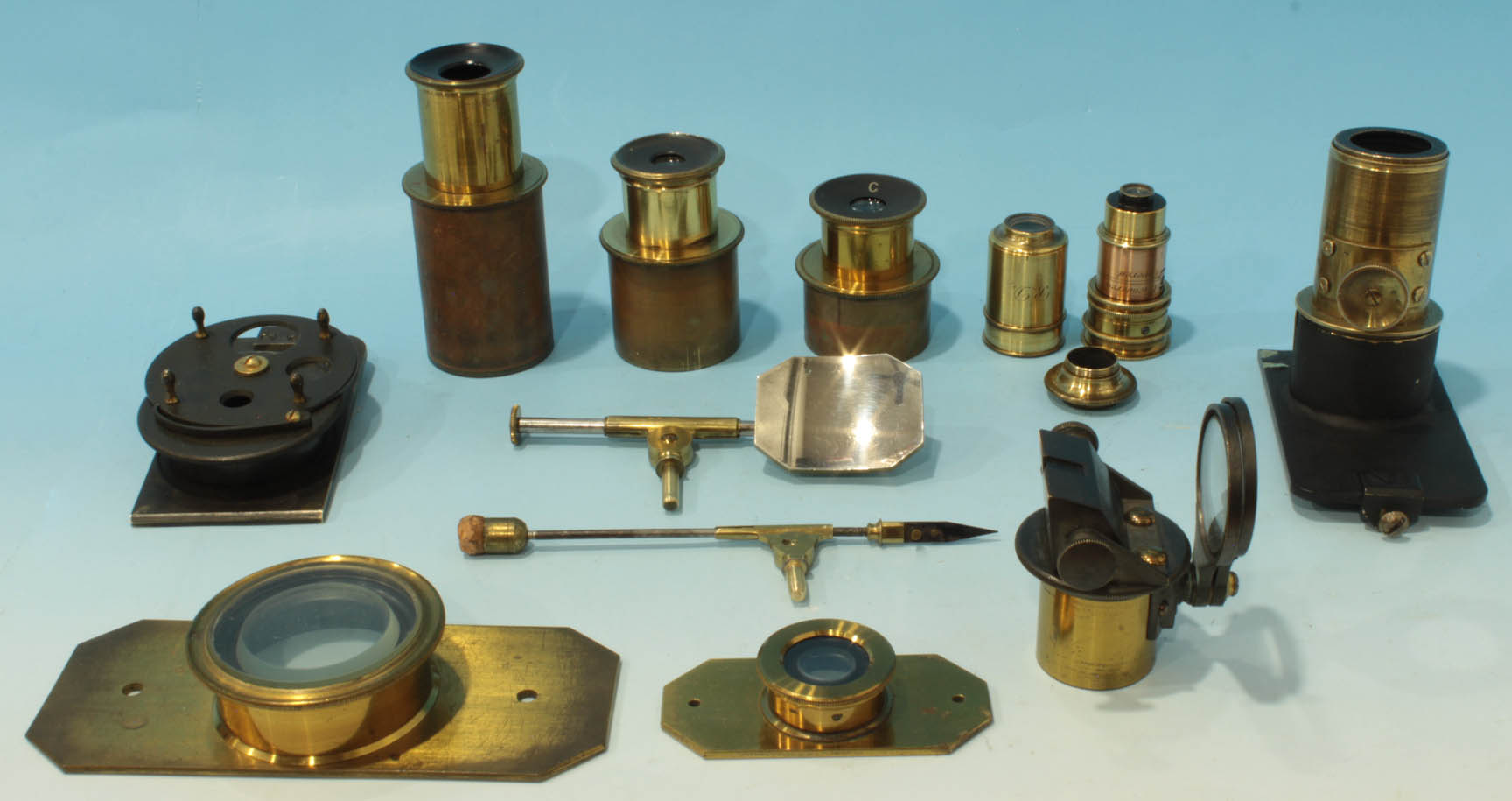
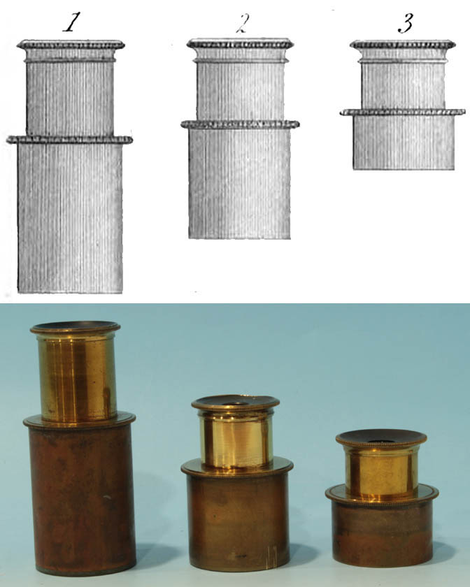
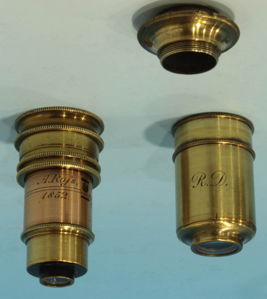
R Dengraved in script on it. I added a 1/4 inch Ross objective from 1852. There are three Ross eyepieces. A Ross camera lucida can replace the cap on the eyepiece. Two original live boxes, referred to in the literature of the time as
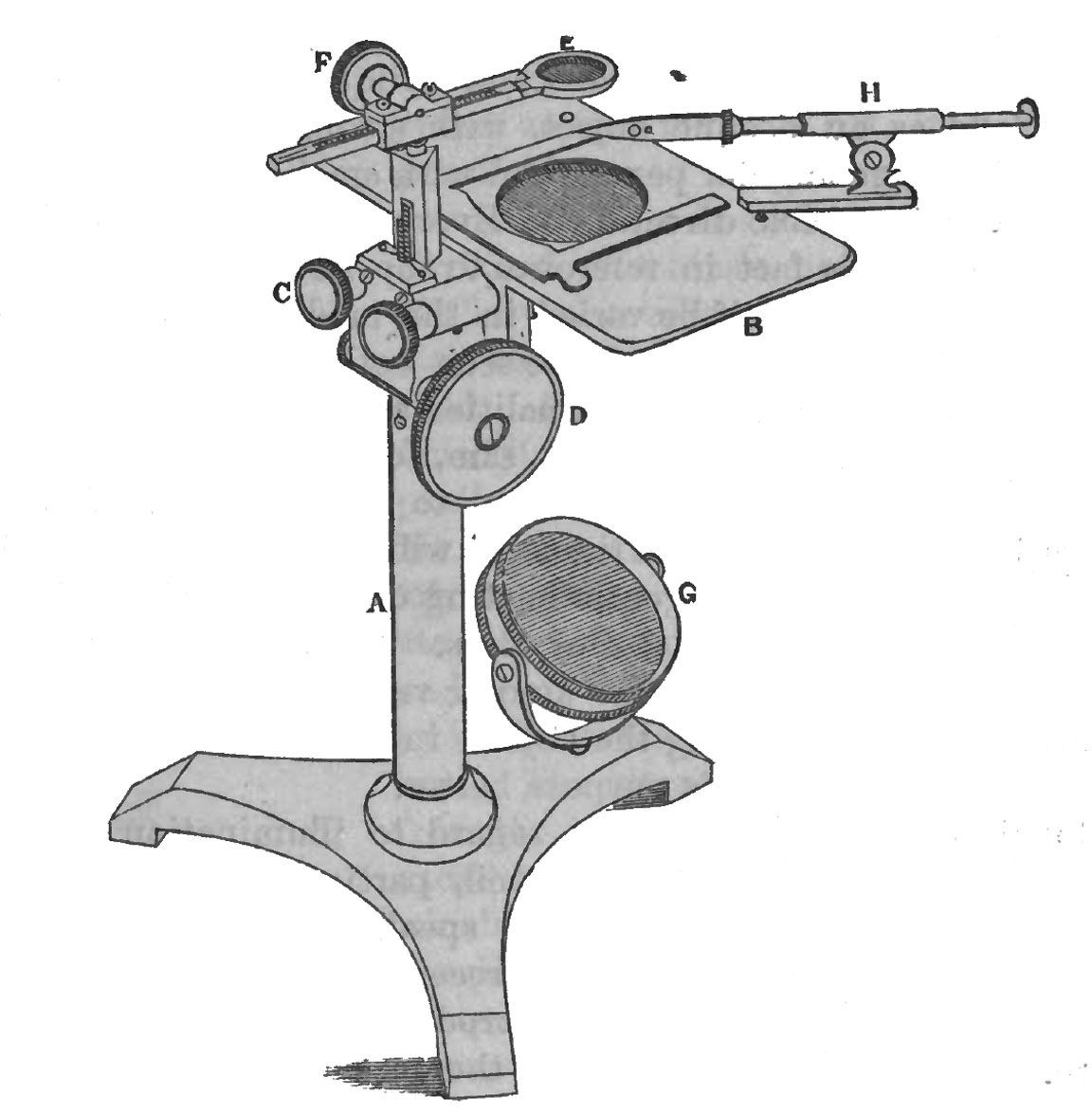
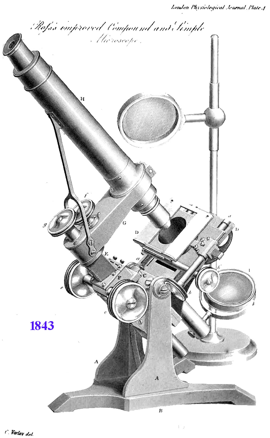
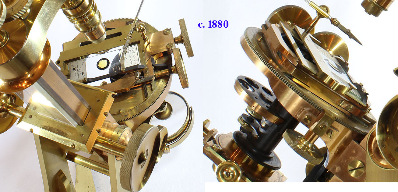
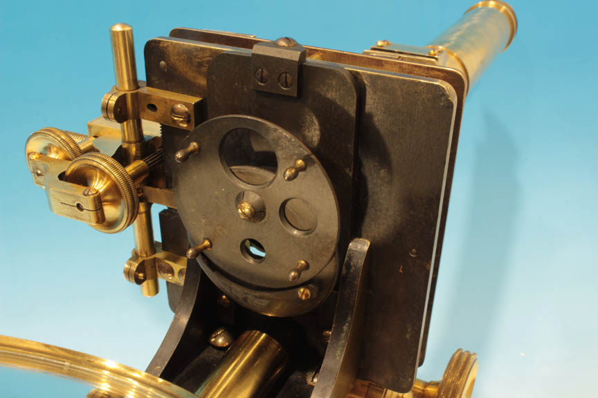
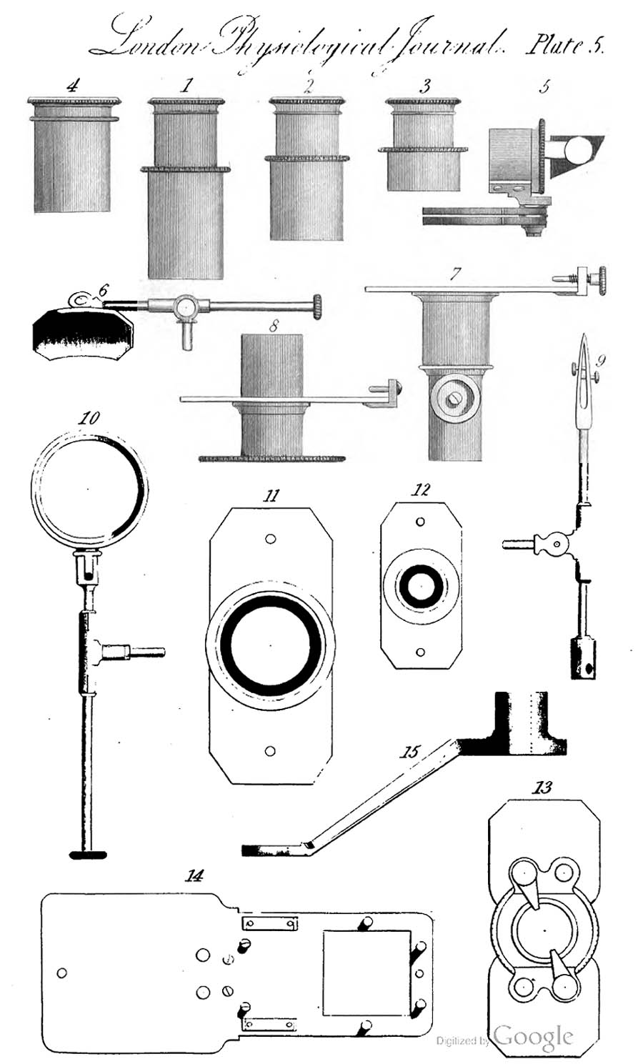
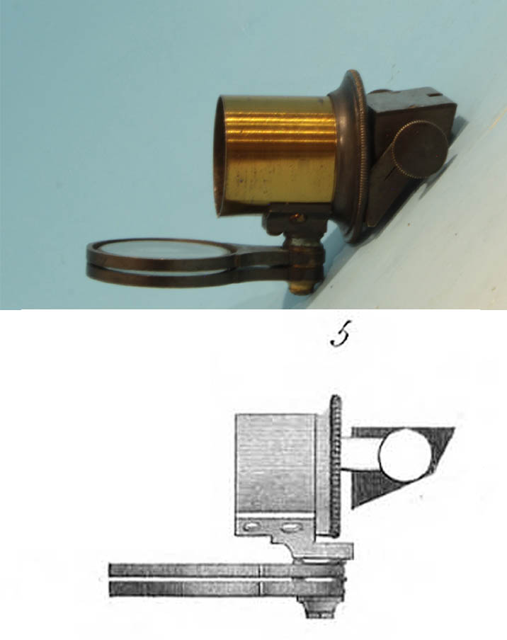
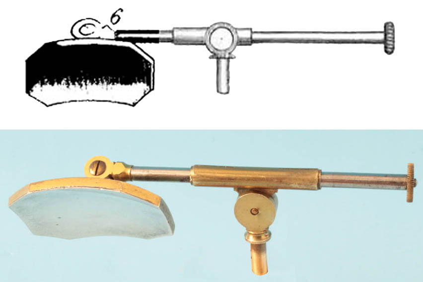
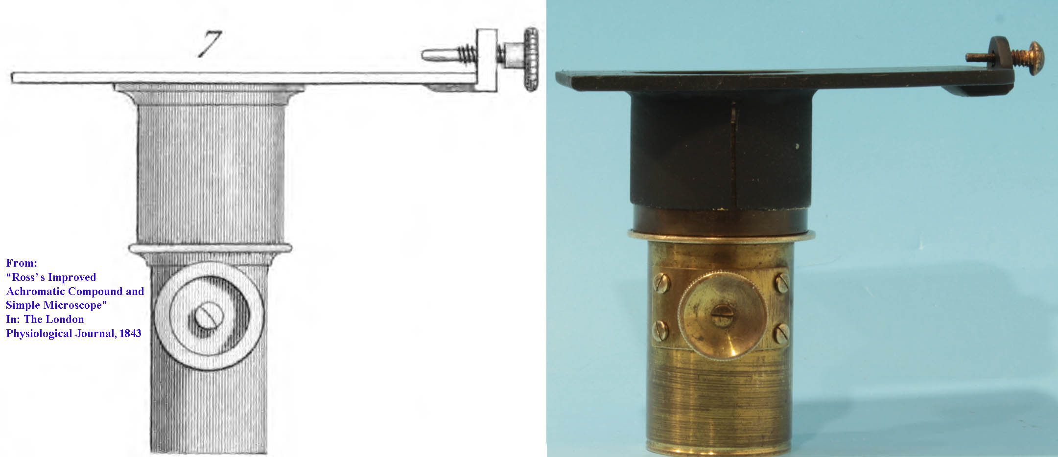
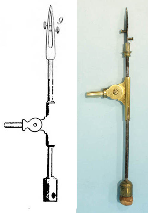
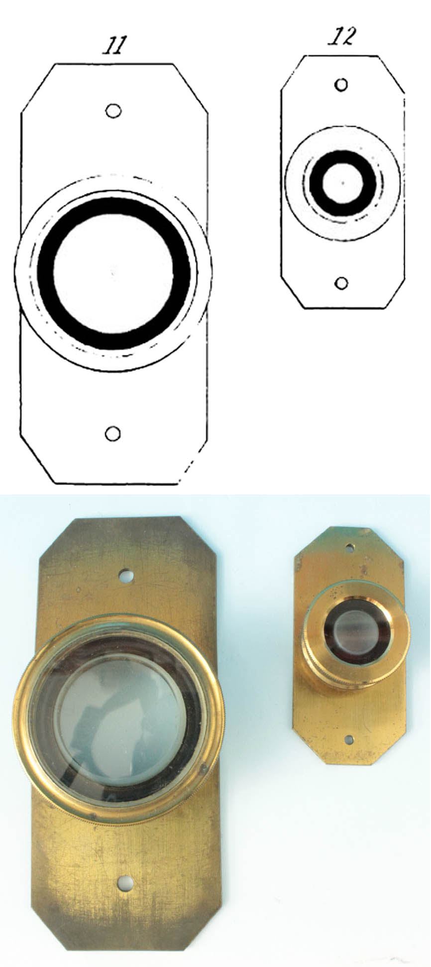
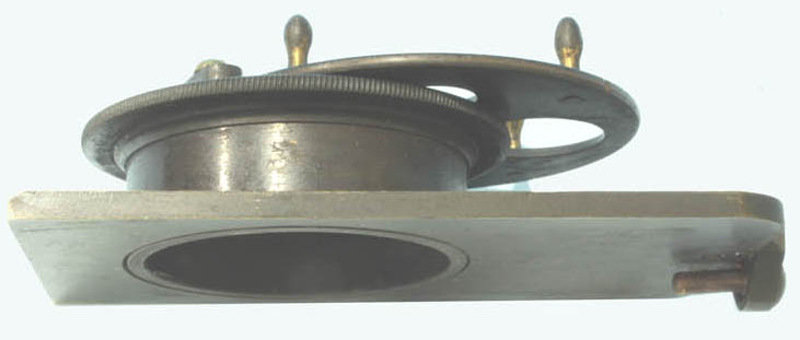
Varley's Animalcula Cagesare also present. Varley's improvement was the black trough around the central disc that serves as a resevoir for the fluid medium that the specimen would be in, reducing the speed at which it would dry out. Another accessory is a silvered stage-mounted side reflector for illuminating opaque objects from above. A rectangular plate with a disk of apertures, slides in along the bottom surface of the stage, held on by two fingers at the back of the stage bottom; this plate, like other substage accessories, has a screw in front to register in a a short round hole at the front of the stage, allowing adjustment for centering in the Y axis as well as providing a third point to hold the plate securely in place. The aperture wheel has four little brass knobs projecting down to rotate it into any of its four positions, each registered by a click-stop. There are three different size openings and one position that has no opening. Additional substage accessories, each on their own rectangular plate would slide into the same position. One of these for example, a condenser with integrated rack and pinion focusing; a fairly accurate facsimile of the latter is also with the microscope, the plate being fabricated anew, and the focusing portion sourced from a group of spare parts and gifted to Barry from Jurriaan. It uses a short objective as a condenser, a 2/3 inch by Swift currently in place. Although the pin in front of the plate provides centering in the Y axis for substage accessories, centering in the X axis is provided by slightly rotating the arm supporting the main tube right or left. Since this movement is in an arc, it may require a slight adjustment in the Y axis after the movement. A stage forceps is also present. As seen in the illustration from 1843 to the left, other accessories could include additional eyepieces, a stage-mounted bullseye condenser, frog plate, a lister-type compressor, and a supplementary arm for use with simple objectives for e.g. dissection. Obviously, additional objectives were also available.
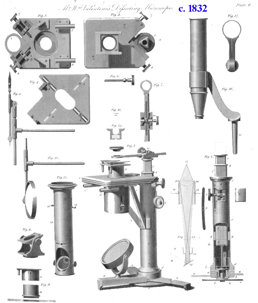
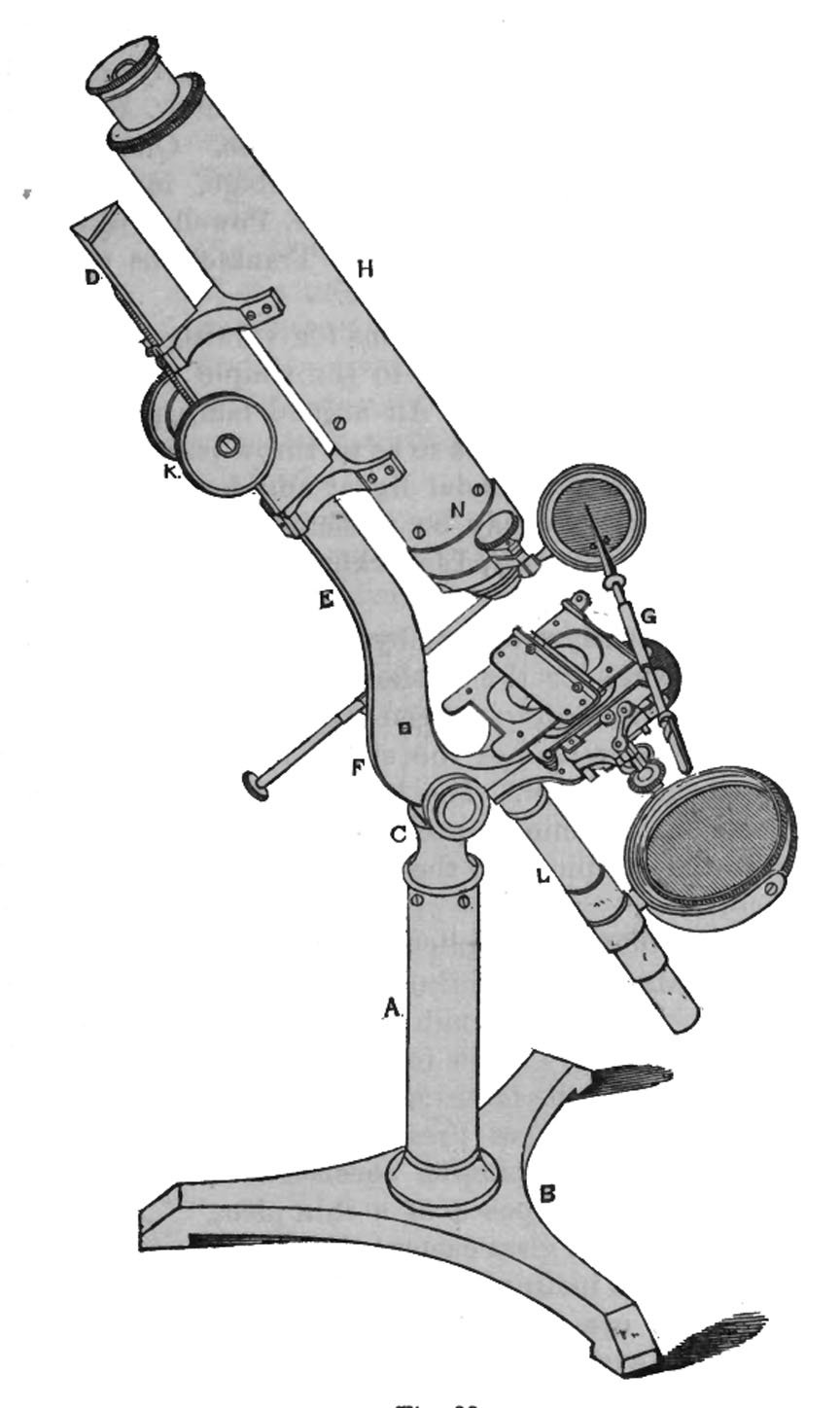
maker for the trade. He quickly became the foremost maker of microscopes in England, producing instruments of good quality. Among the earliest known Ross microscopes, dating to about 1831-2, are a simple and compound microscope for dissection designed by the botanist William Valentine. This microscope was not inclinable and was focused via a knob under the foot, a feature previously found in some of the microscopes of the 1700s. Its description was published in 1832 in the Transactions of the Society of Arts, Manufactures,Commerce &c., Vol XLVIII and is shown here to the left. Ross is well known for his invention of the correction collar for objectives, an early example of which is in this collection.
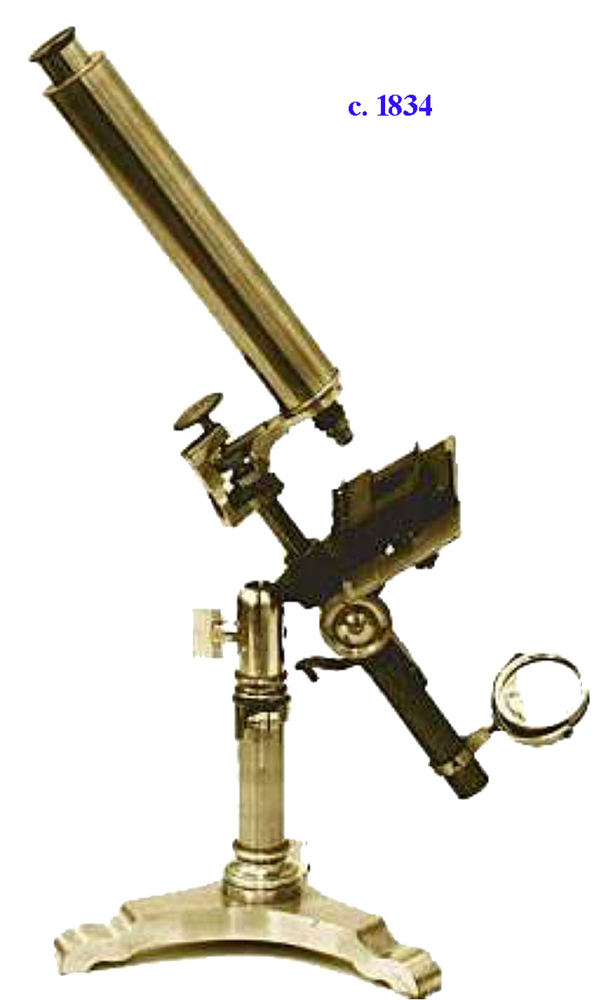
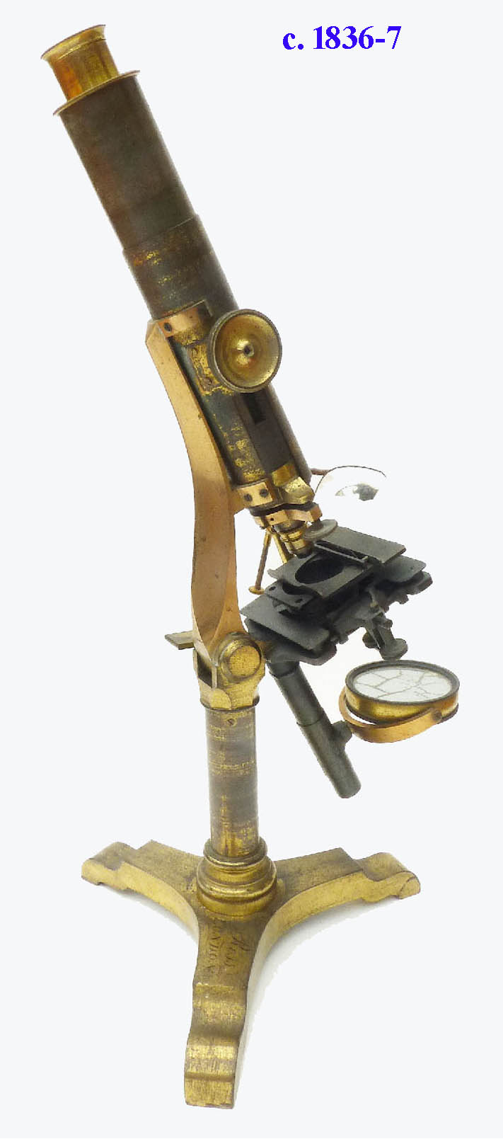
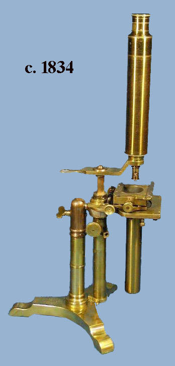 His next microscopes were variations on the
 Jones Most Improvedplan. But instead of a simple inclination joint, these microscopes featured a ball-and-socket inclination joint and were made until the mid 1830s. They usually featured a flat tripod foot, but a microscope of this type with a round foot, likely made by Ross, but signed by Cary is in this collection.
Iron Microscope