| DESCRIPTION | HISTORY | CONDITION |
Please Click On Any Picture for a Larger Version, where available
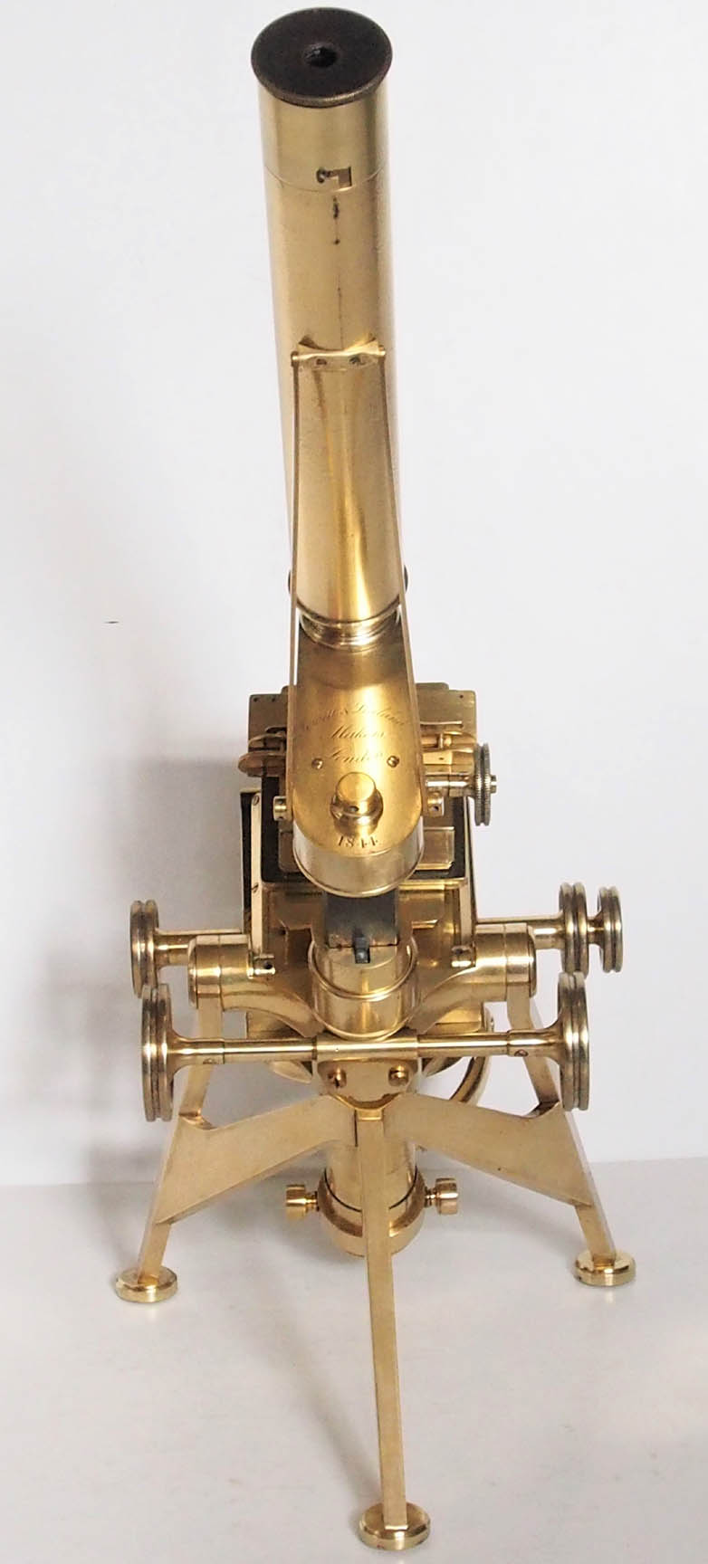
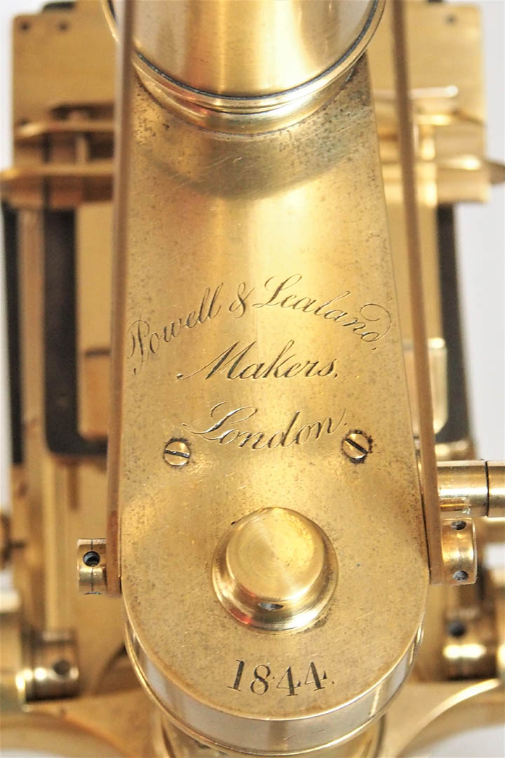 This microscope is signed and dated on the arm:
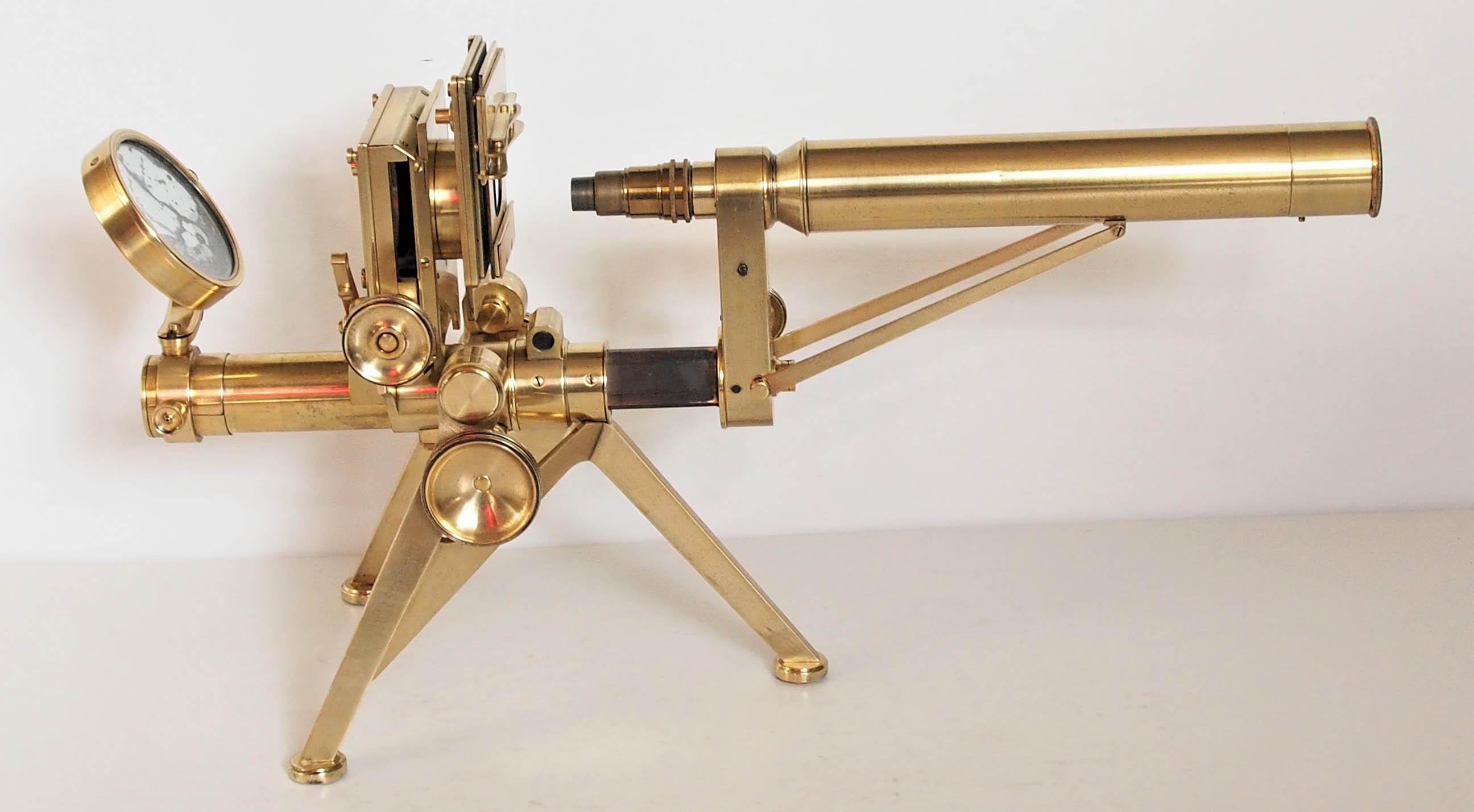
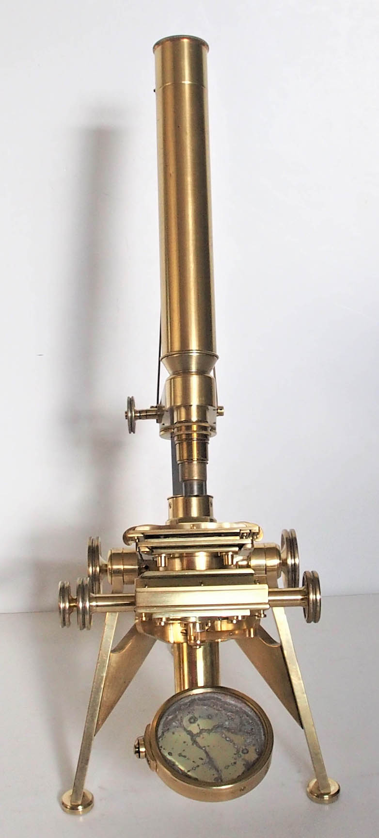
 Powell & Lealand, Makers, London, 1844. It is supported by what has come to be known as an
English tripodfoot with a span of about 16 cm (6.5 in.) right to left, and 20 cm (7 7/8 in) from either front leg to the rear leg (outside edge to outside edge). Each foot pad is of round profile and cork shod. On the later and larger models, including the Improved First Class Microscope, the No. 1 and No. 2, the pads were rectangular. Only the No. 3 retained the round pads.
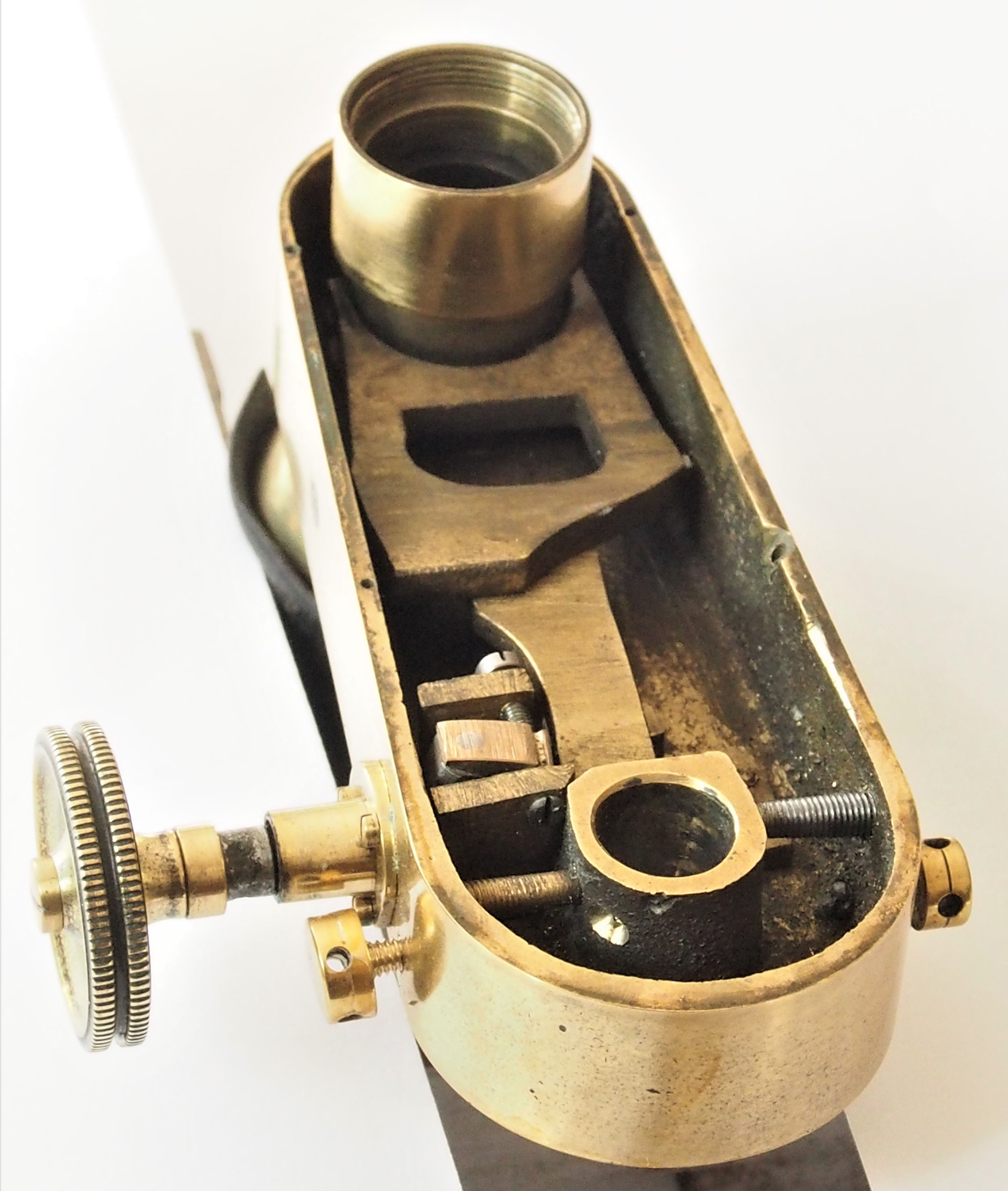 Fine focus is by a horizontally-oriented knob on the right side of the arm acting on an L-shaped piece inside the arm to move a long lever to the nosepiece. This mechanism was introduced shortly after the original mechanism in which the knob acted on a wedge lifting or lowering the long lever. That lever mechanism is unsatisfactory however, as it tends to bind as soon as the lubricant used wears off. For this reason, this example was upgraded by modifying the original parts and adding the new mechanism acting on the lever; evidence of the modification can be seen including some marks inside the arm where the wedge mechanism previously sat. P & L made these modifications to satisfy many of their customers during the early days of this model. The side fine adjustment, with or without modification was continued until 1848 when P & L started to provide fine adjustments on the top of the limb, acting directly on the long lever. Microscopes from 1848 and 1849 are known to have either the side or the top fine adjustment. By 1850 only the top fine adjustment was used. The fine adjustment page illustrates how this 1844 modification of the fine adjusment works and the page comparing the original 1843 side fine adjustment to the revised type from 1844 illustrates both types together.
screwdoes not drive a nut but rather the follower, a spring loaded V-shaped piece attached to the moving part of the stage.
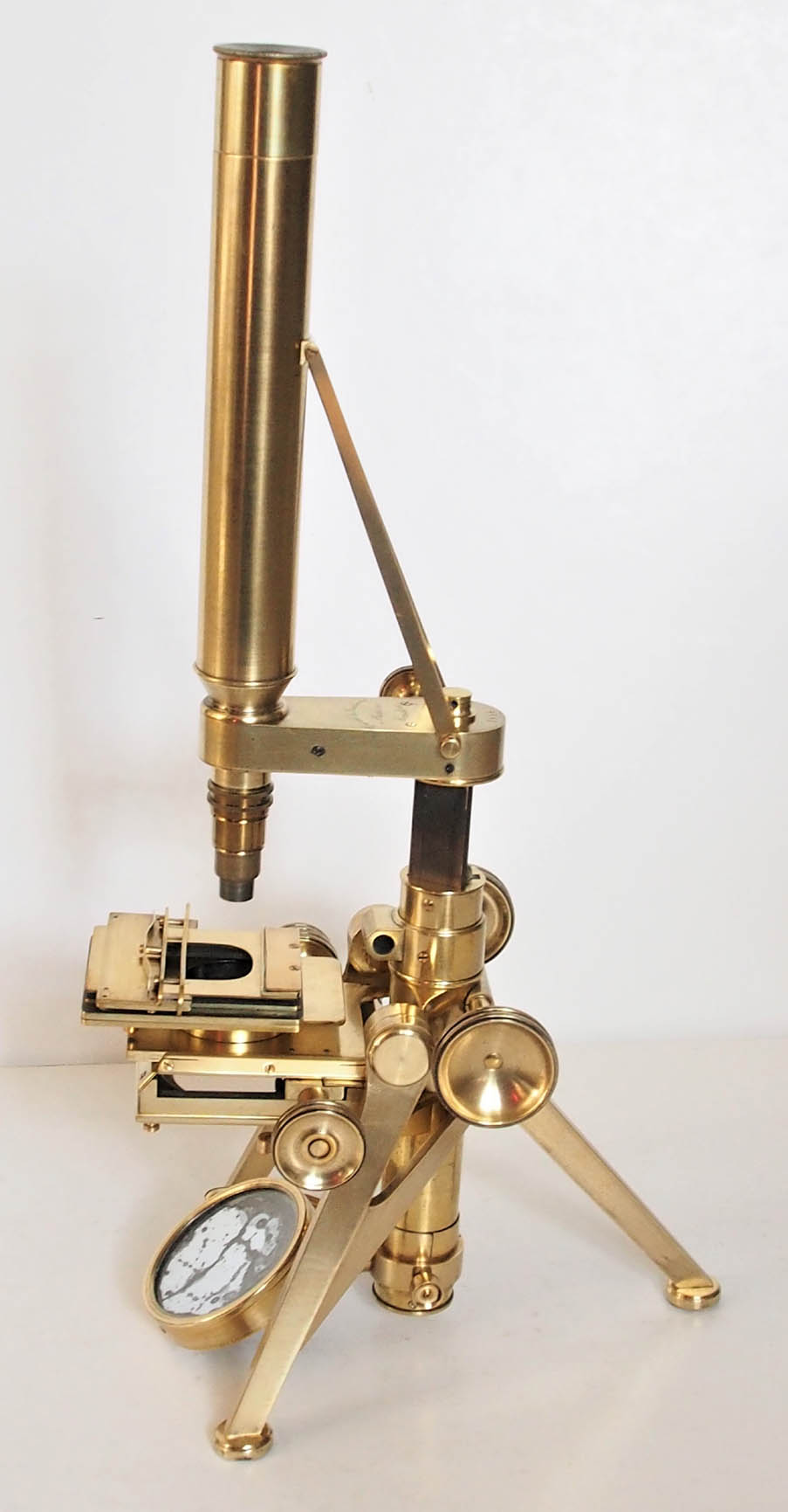
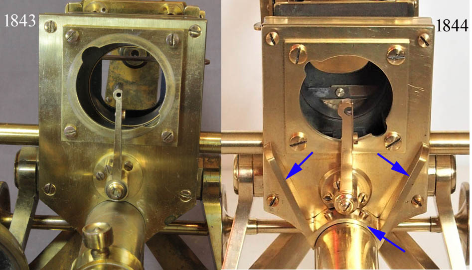 The underside of the stage has an attached plate with a circular aperture having opposed notches that accepts the male bayonet fitting on the larger substage accessories. This 1844 model differs from the 1843 model in that a V-shaped brace screwed to the tailpiece gives added support(blue arrows) to the substage. In addition, the support for the darkwells has been modified to fit in the same location by removing part of it that fits against the brace support. These accessories are shown on the page about the earlier 1843 model. Under the stage, is a swing-in holder for darkwells very similar to the system used later by J.B. Dancer, among others.
 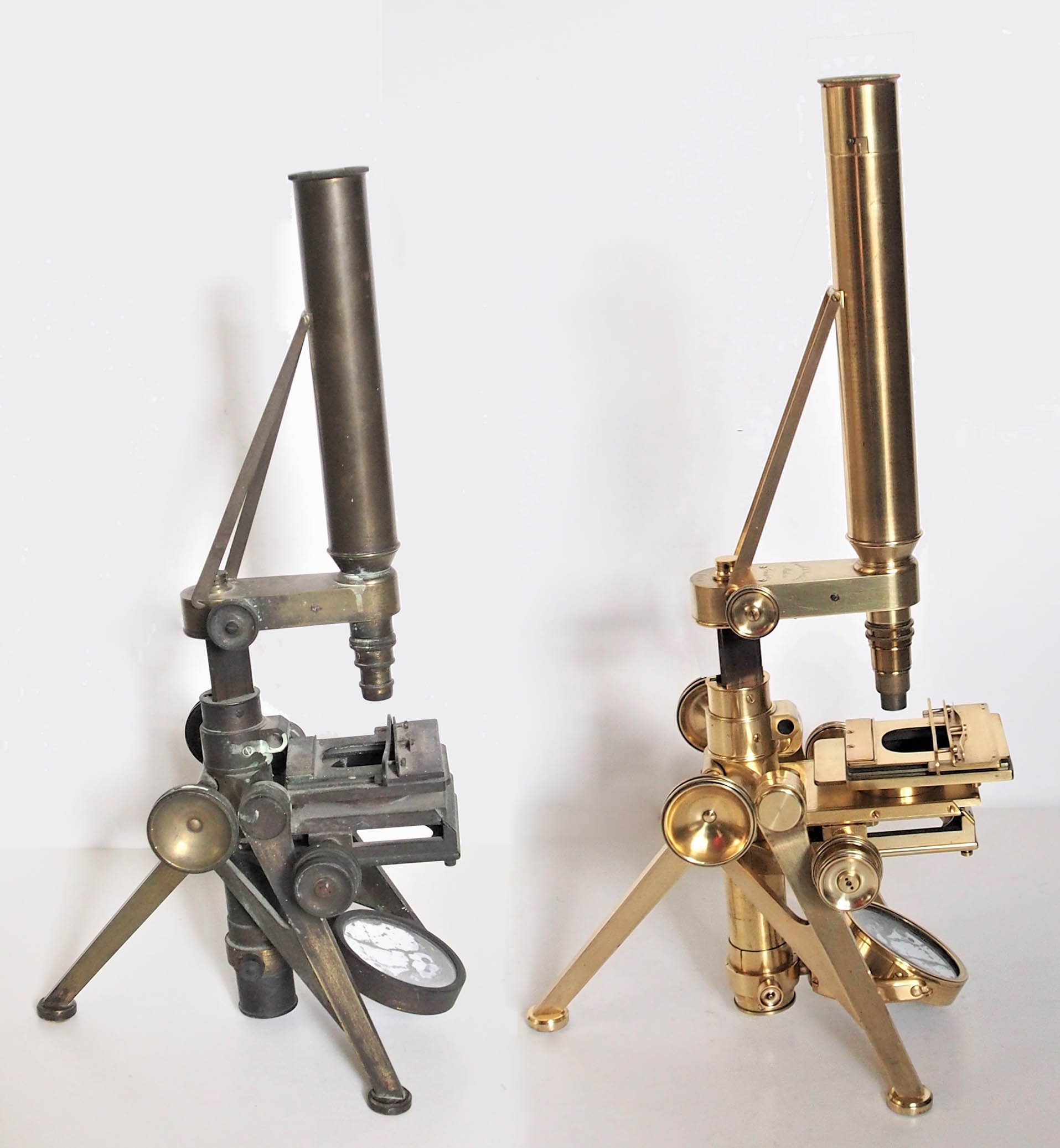 This microscope, considering it is more than 175 years old, is in good condition. When originally received however(left of illustration), all the lacquer was gone and the entire stand was heavily oxidized. the tripod was bent, and it lacked the swinging darkwell holder. Dr de Groot corrected the tripod bend, replaced the missing darkwell holder with a newly fabricated one, and completely restored the finish of this microscope to a state very much like the original. Early P & L microscopes are all uncommon.
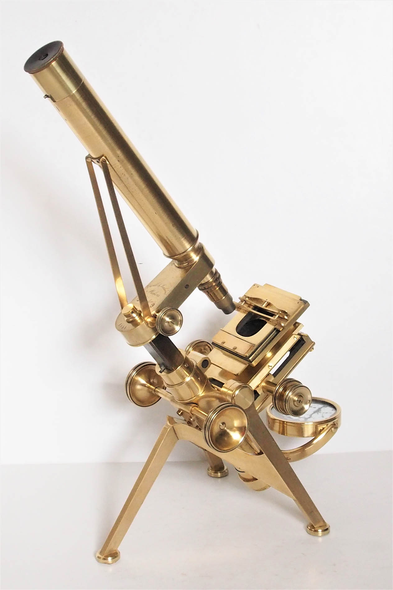
 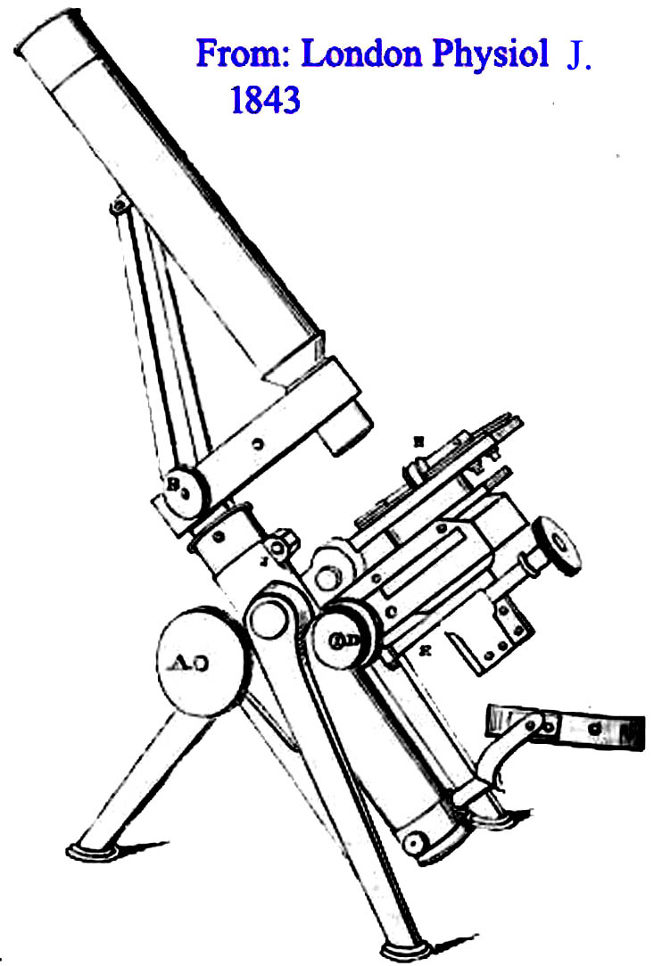 Although larger model microscope stands had been produced by Hugh Powell, notably the massive stand commissioned by the Royal Microscopical Society in 1840, what is now known as the No 1 Model was a direct development of Powell & Lealands 'New Microscope' of 1843, the model featured at the top of this web page. These microscopes of 1843 formed the prototypes of the famous group of stands, later to be called the Powell & Lealand Number 1, Number 2, and Number 3. In fact, this microscope is often confused with the later Number 3 stand, which it resembles in many ways. As shown here, this form of stand was first described in the 1843 November issue of The London Physiological Journal as 'Powell & Lealands New microscope'. This stand is supported by a lighter, but still very strong, version of the tripod, than P & L's later first class stands. It carries the body on trunnions, and has a transverse arm, which contains the long lever connected to the nosepiece.
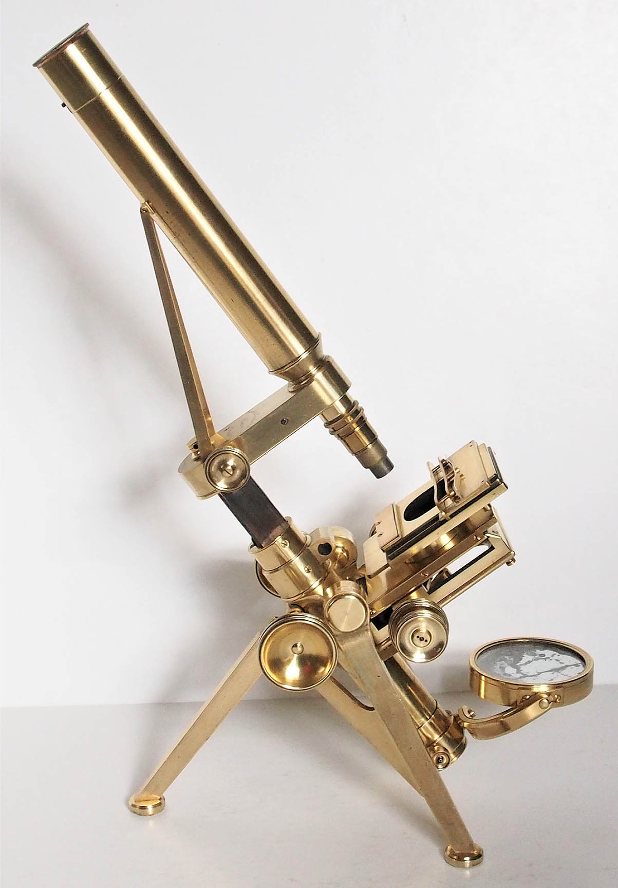
Initially, the fine adjustment control was placed on the side of the arm, acting on the long lever via a sliding wedge. As illustrated here, from 1844 onwards, examples are known of a revised form of fine adjustment, which utilizes a tilting L-shaped piece of brass which transfers the motion of the threaded knob to lift the long lever. The fine adjustment was changed to the familiar vertical position on top of the arm, with the threaded knob acting directly on the long lever in 1848 and 1849. Some examples engraved with these years of manufacture are known which still feature the side fine adjustment. From 1850 onwards, all fine adjustments are located on the top of the arm. From the start of production in 1843, the microscope tube was supported by a set of diagonal stabilizing struts extending from the back of the arm to the upper third of the tube. Sometime in the 1860's these were abandoned when it was realized that they added little to stability.
Although larger model microscope stands had been produced by Hugh Powell, notably the massive stand commissioned by the Royal Microscopical Society in 1840, what is now known as the No 1 Model was a direct development of Powell & Lealands 'New Microscope' of 1843, the model featured at the top of this web page. These microscopes of 1843 formed the prototypes of the famous group of stands, later to be called the Powell & Lealand Number 1, Number 2, and Number 3. In fact, this microscope is often confused with the later Number 3 stand, which it resembles in many ways. As shown here, this form of stand was first described in the 1843 November issue of The London Physiological Journal as 'Powell & Lealands New microscope'. This stand is supported by a lighter, but still very strong, version of the tripod, than P & L's later first class stands. It carries the body on trunnions, and has a transverse arm, which contains the long lever connected to the nosepiece.
Initially, the fine adjustment control was placed on the side of the arm, acting on the long lever via a sliding wedge. As illustrated here, from 1844 onwards, examples are known of a revised form of fine adjustment, which utilizes a tilting L-shaped piece of brass which transfers the motion of the threaded knob to lift the long lever. The fine adjustment was changed to the familiar vertical position on top of the arm, with the threaded knob acting directly on the long lever in 1848 and 1849. Some examples engraved with these years of manufacture are known which still feature the side fine adjustment. From 1850 onwards, all fine adjustments are located on the top of the arm. From the start of production in 1843, the microscope tube was supported by a set of diagonal stabilizing struts extending from the back of the arm to the upper third of the tube. Sometime in the 1860's these were abandoned when it was realized that they added little to stability. 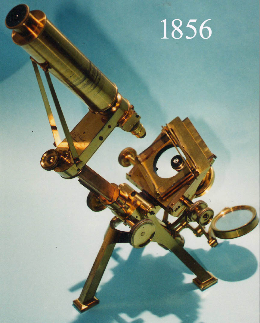 Powell & Lealand did not enter the 1851 Great Exhibition, but it is believed that during this time they worked on a larger model based on the original design. Dated examples are extant from this period, with the more solid rectangular feet as in the later No 2 stand, either with or without the supporting struts. These could be regarded as the 'proto-No 1/No 2 stands', from which the later models were developed. Two examples of these, called the
 Improved Large First Class Microscopeare found on this site, and they still have struts supporting the tube. As seen in the image to the left, this stand of 1856, is essentially the same as the 1843 stand, other than the position of the fine focus knob, the design of a heftier tripod, and the rectangular and heavier tripod legs. More importantly though, it now had a separate rack and pinion substage, so substage accessories no longer were attached to the bottom of the stage itself.
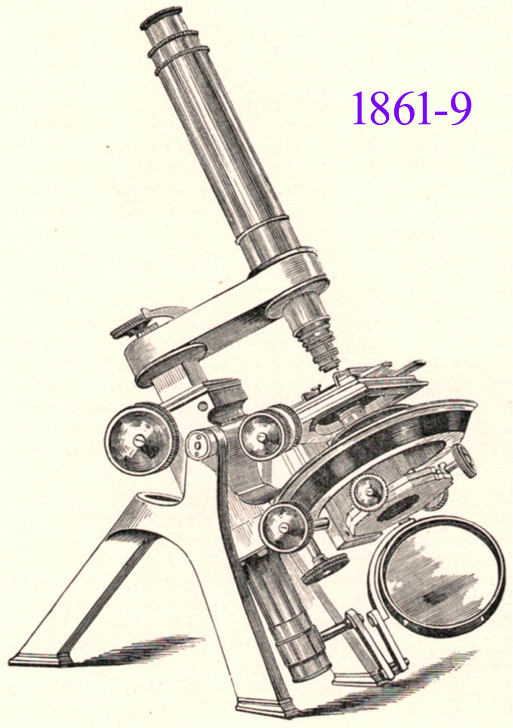 The next model (left), was worked on at odd times, and appeared in 1861. It was similar in outline and appearance to the final No 1 design, save for the massive ring attached to the limb, within which there was a second ring carrying the stage to which the substage was attached, allowing both to be rotated by the same rack-and-pinion movement, with separate rotation also provided for the substage. An example of this model was ordered by the Radcliffe Library for use by The University Museum, Oxford, in 1864, together with a 1/50-inch objective amongst the accessories. We should also note that Wenham's binocular, first seen about 1860 was added to the Powell & Lealand options and further improved upon over the years. The No 1 model continued to be made as described above until the definitive version of the No 1 model stand was put on the market in 1869. The main modifications involved the construction of the rotating stage, which this time was mounted in the same plane as the ring, and there was a separate carrier for the centering and rotating substage, attached below the stage now, and not rotating with it as in the previous model.
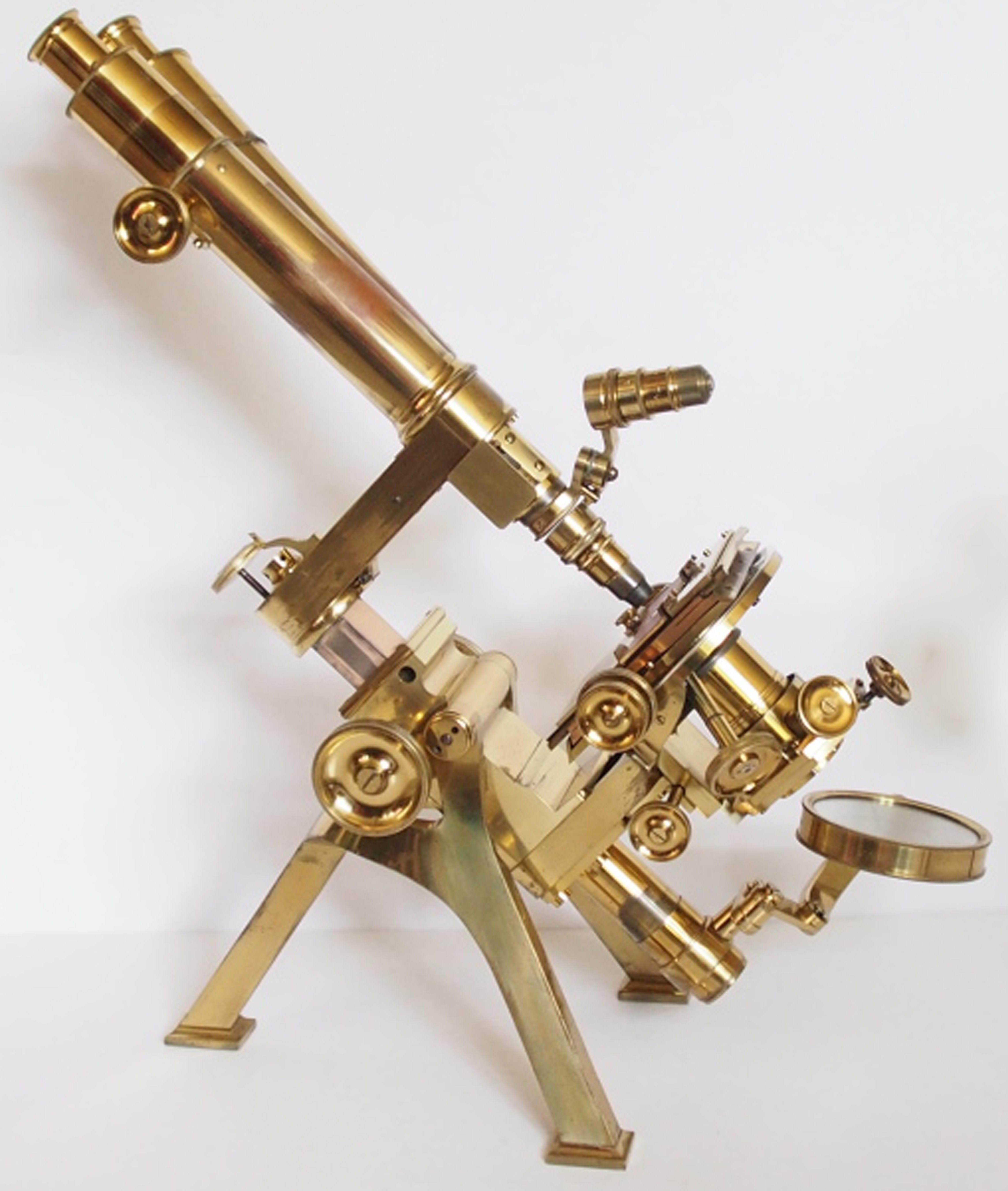 In this final form, the Powell & Lealand No 1 microscope continued to be made unchanged for another 40 years, until the firm quietly faded out of existence during the first decade of the 20th Century. The only additions, were an optional fine adjustment to the substage (1882), rack work to the monocular draw tube (1887), and diagonal rack work to the coarse adjustment, all at the suggestion of E.M. Nelson, an eminent microscopist, and user of this model. For more information about P & L, including a detailed and illustrated description of the final form of the No 1, as well as a more detailed history, please see the Powell & Lealand No. 1 page