| DESCRIPTION | HISTORY |
Please Click On Any Picture for a Larger Version
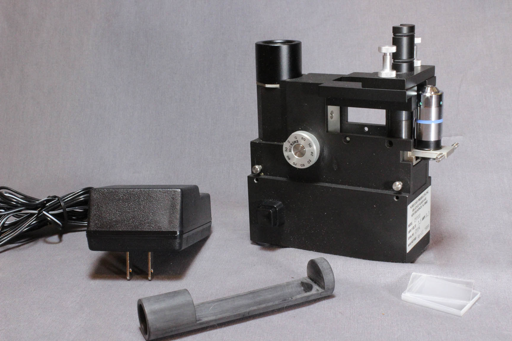
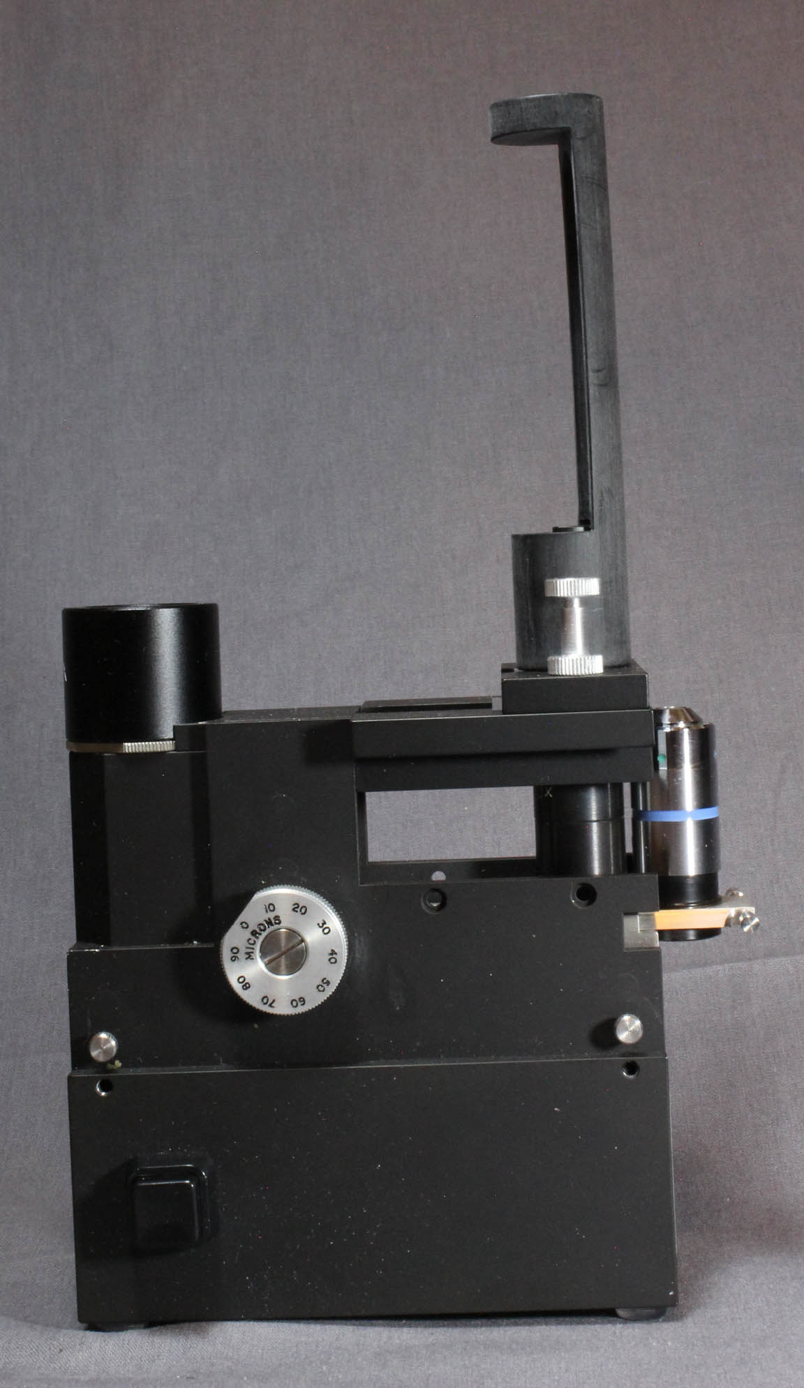
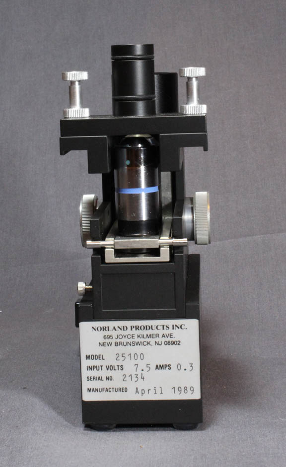
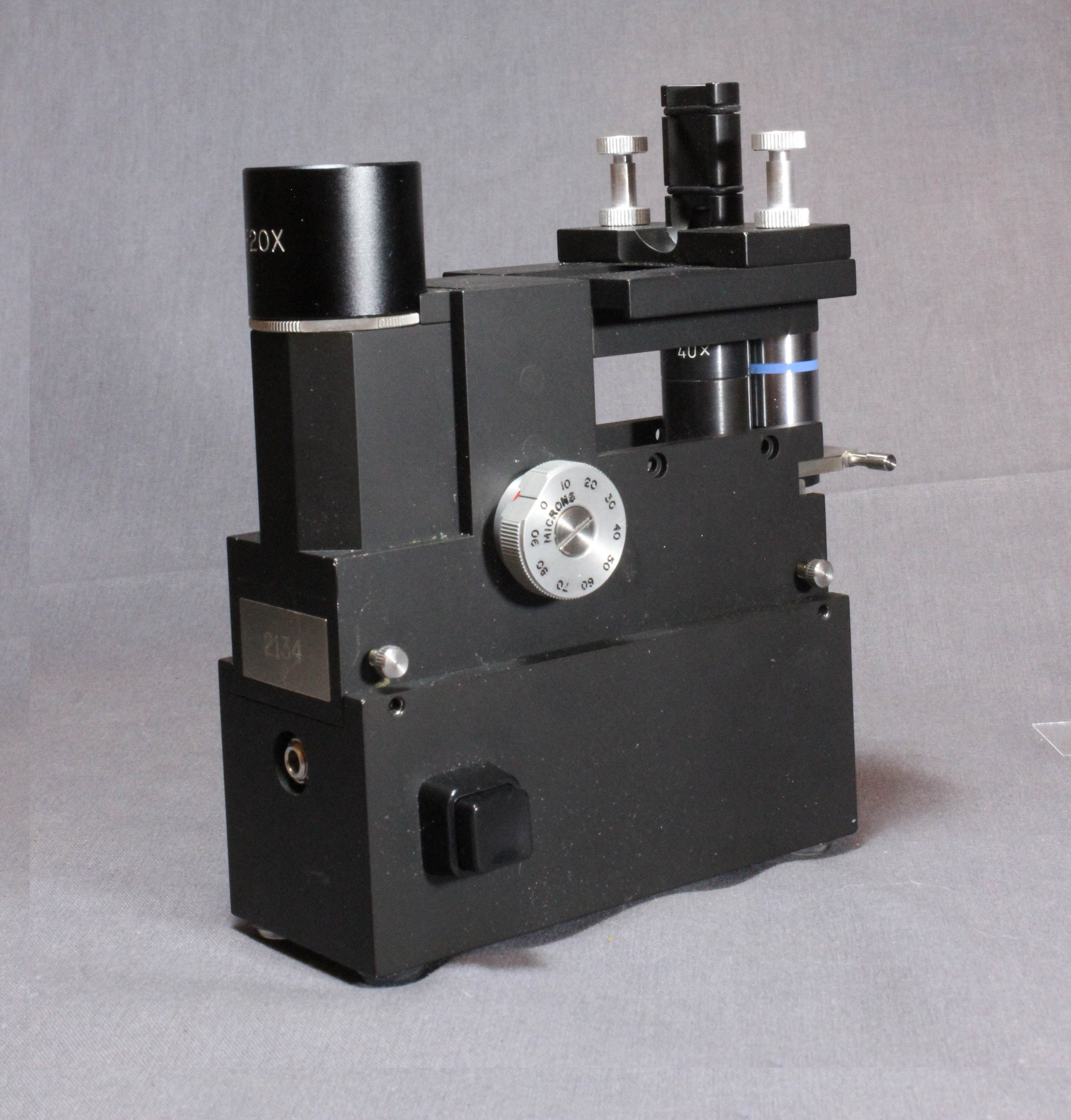
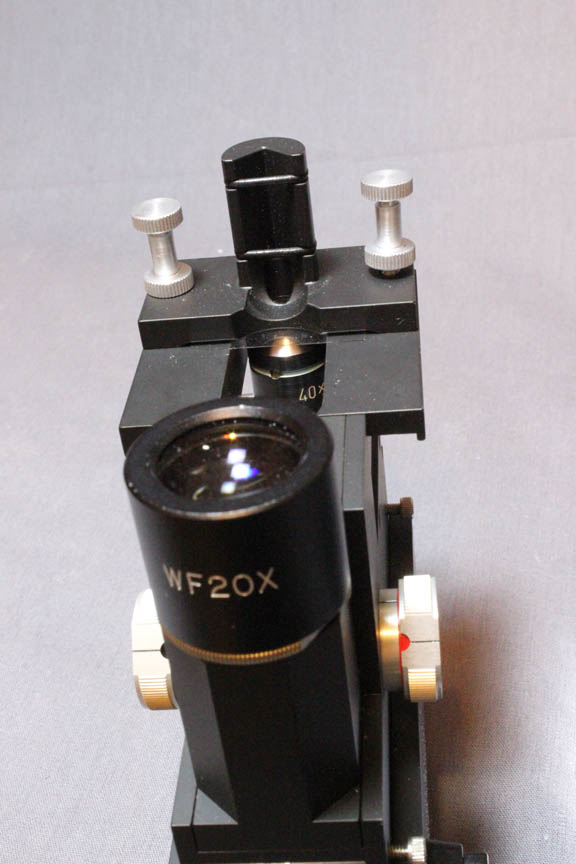
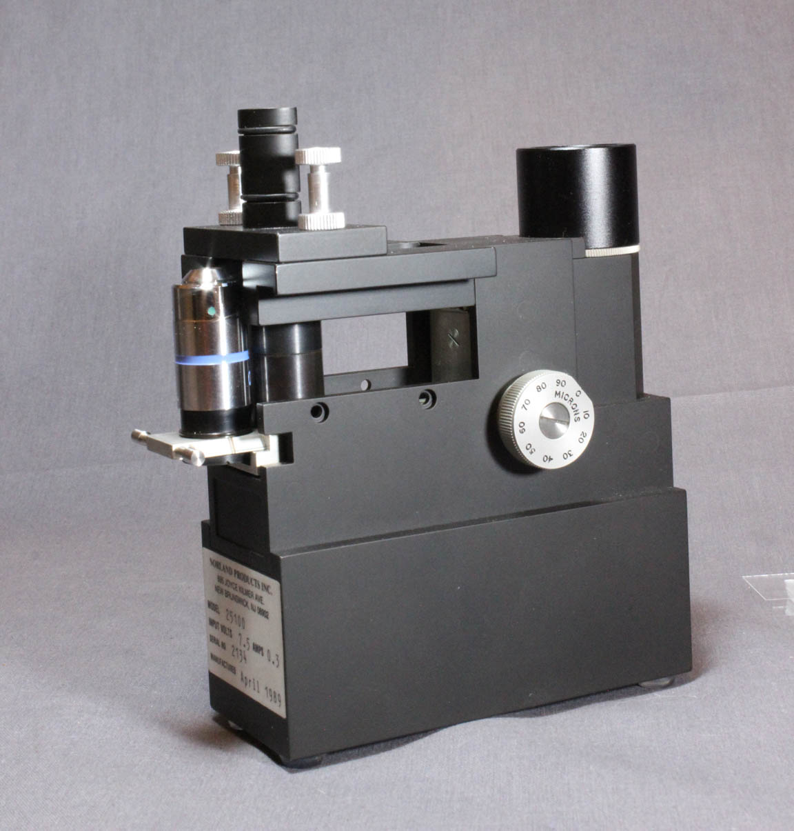
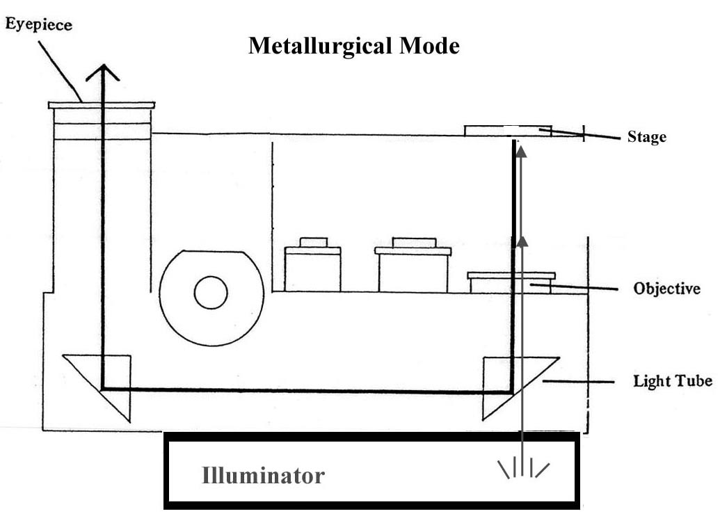 The Interferometer Microscope is basically in the same format as the metallurgical microscope, except that the light source is a monochromatic red light and the stage surface has attached to it a fitting for holding a reference flat horizontally with the fiber oriented vertically held in a grooved fitting. There is one eyepiece, and two objectives. The eyepiece is a 20X wide field type. The two objectives are a X and a X. The microscope came standard with a 40X objective, 10X and 20X objectives were additional options. Also included is an AC power supply and an extension for the fitting to hold the fiber. The red LED is turned on and off via a square pushbutton on the right side of the micrscope.
 Ideal for checking cleaver performance. A unique, small, portable interferometer for checking the cleaved ends of optical fibres. It is based on a commercially available microscope with illumination provided by a red LED. Battery or mains versions are available. An interference pattern is formed by the wedge-shaped air gap between the fibre end face and a reference flat. By counting the number of fringes, the end angle can be deduced (71 /2 fringes across a 125gm diameter fibre is equivalent to one degree). The fibre is held perpendicular to the reference flat by a glass capillary which is itself a sliding fit into an accurately machined block. Using different capillaries, any size of fibre can be examined.The shape and distribution of the fringes also gives data on the topography of the end face and consequently valuable information on the state of the blade of the cleaving tool.