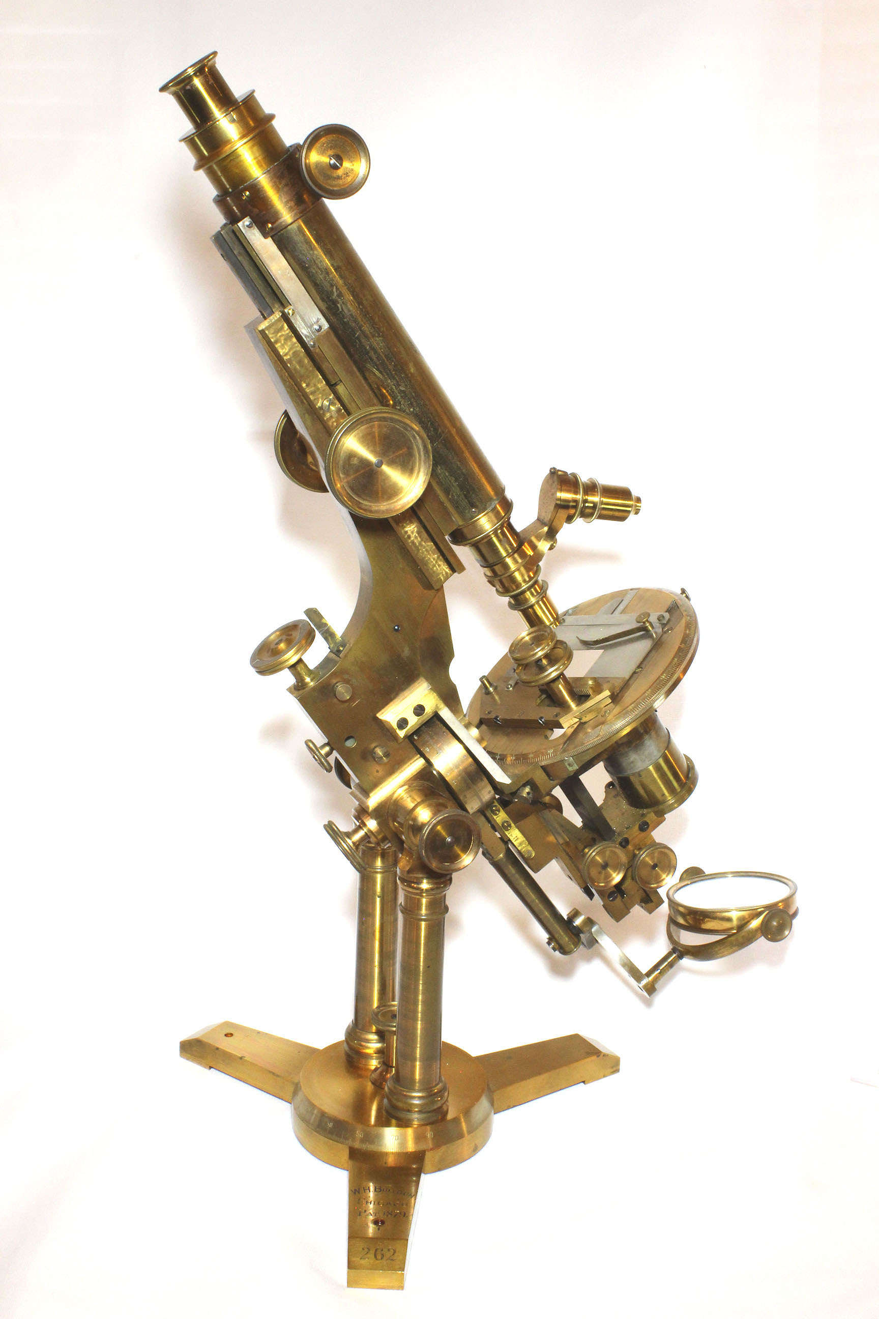
BULLOCH CONGRESS MICROSCOPE
c. 1882
SIGNED: W.H. BULLOCH, Chicago, PAT. 1879
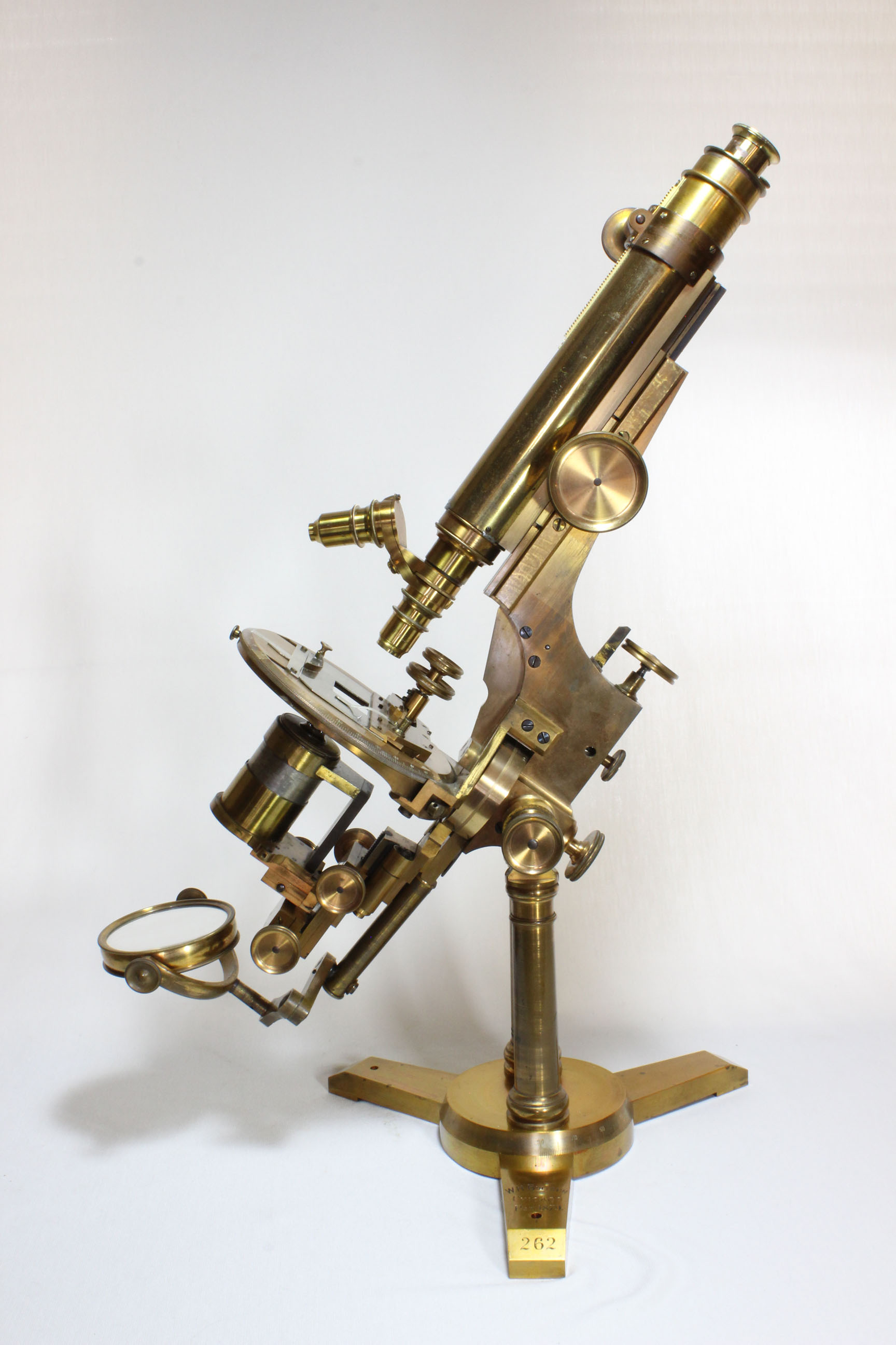
SERIAL NUMBER: 262
MODEL: CONGRESS STAND
PLEASE CLICK ON ANY IMAGE FOR ENLARGED AND/OR MORE IMAGES
DESCRIPTION:
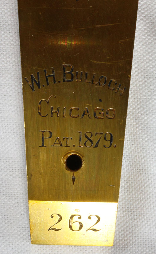
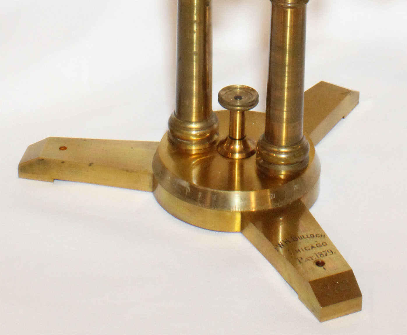 Signed on the flat tripod foot:
 W.H.Bulloch, Chicago.
In Addition, Stamped below the Signature:
PAT. 1879
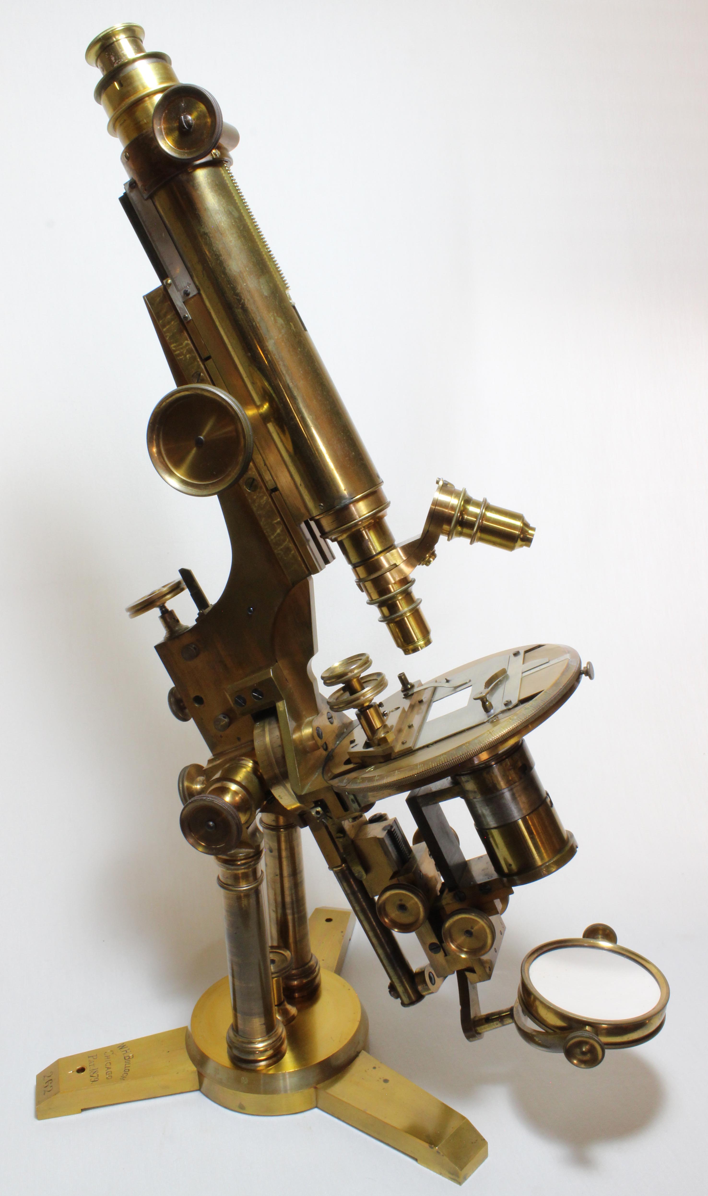
. Numbered 262 on the angular edge of one of the three toes. The stand is supported by two pillars screwed in to a calibrated round plate with silvered scale, which rotates on the foot and has a
locking knob in the center. Two of the three toes have had a hole drilled in them to allow the microscope to be screwed down to solid table top.
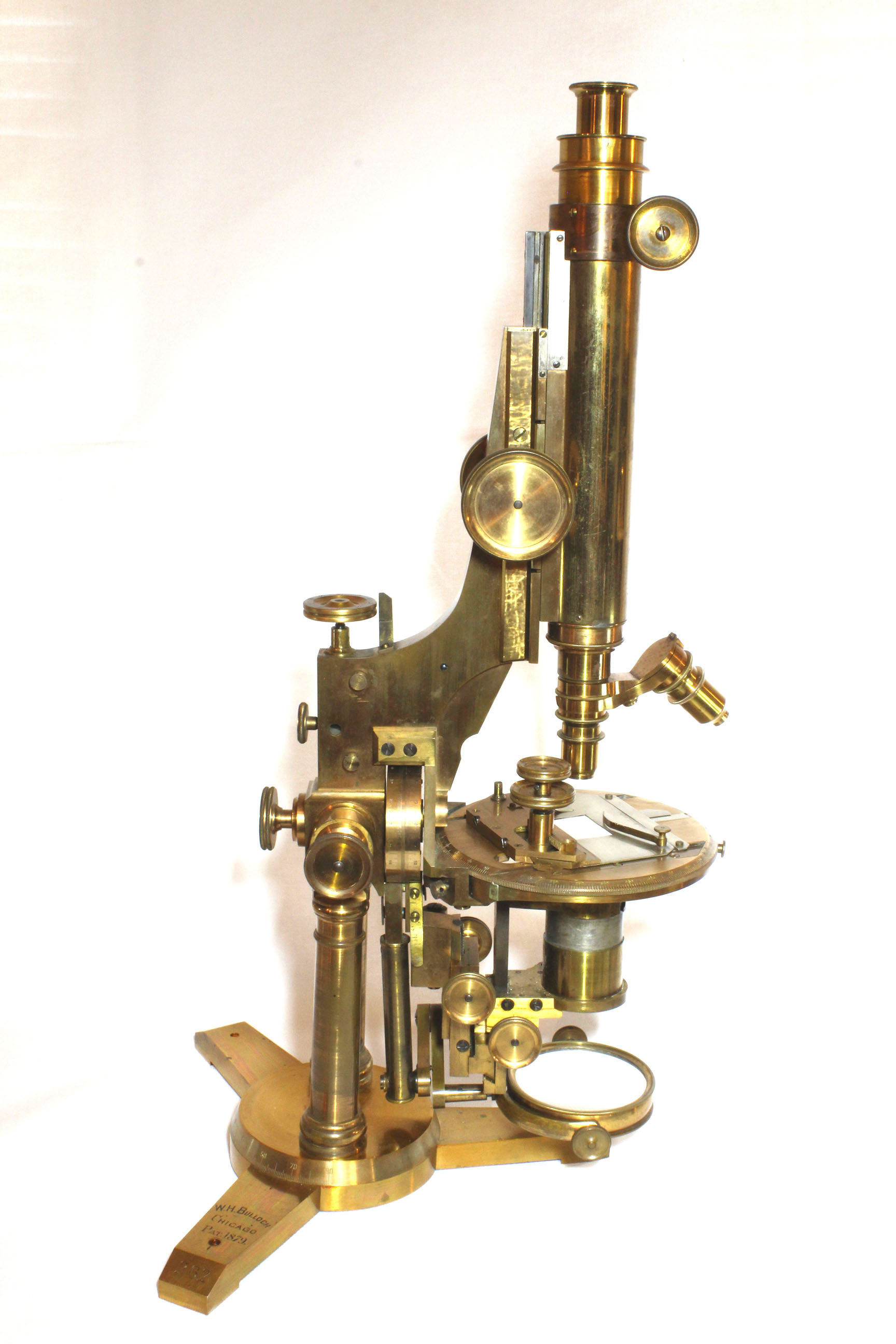
The massive Lister limb is supported
through the trunnion joint at the top of the pillars with knurled knobs on each side to allow easy adjustment of the tension. A knurled knob on the rear of the limb controls the tension of the swinging substage fittings. A second knurled knob adjusts to hold accessories attached to the limb through a hole, such as would be the case for a side reflector, for example. This feature is quite similar to the provision
on the early James Smith microscope in this collection.
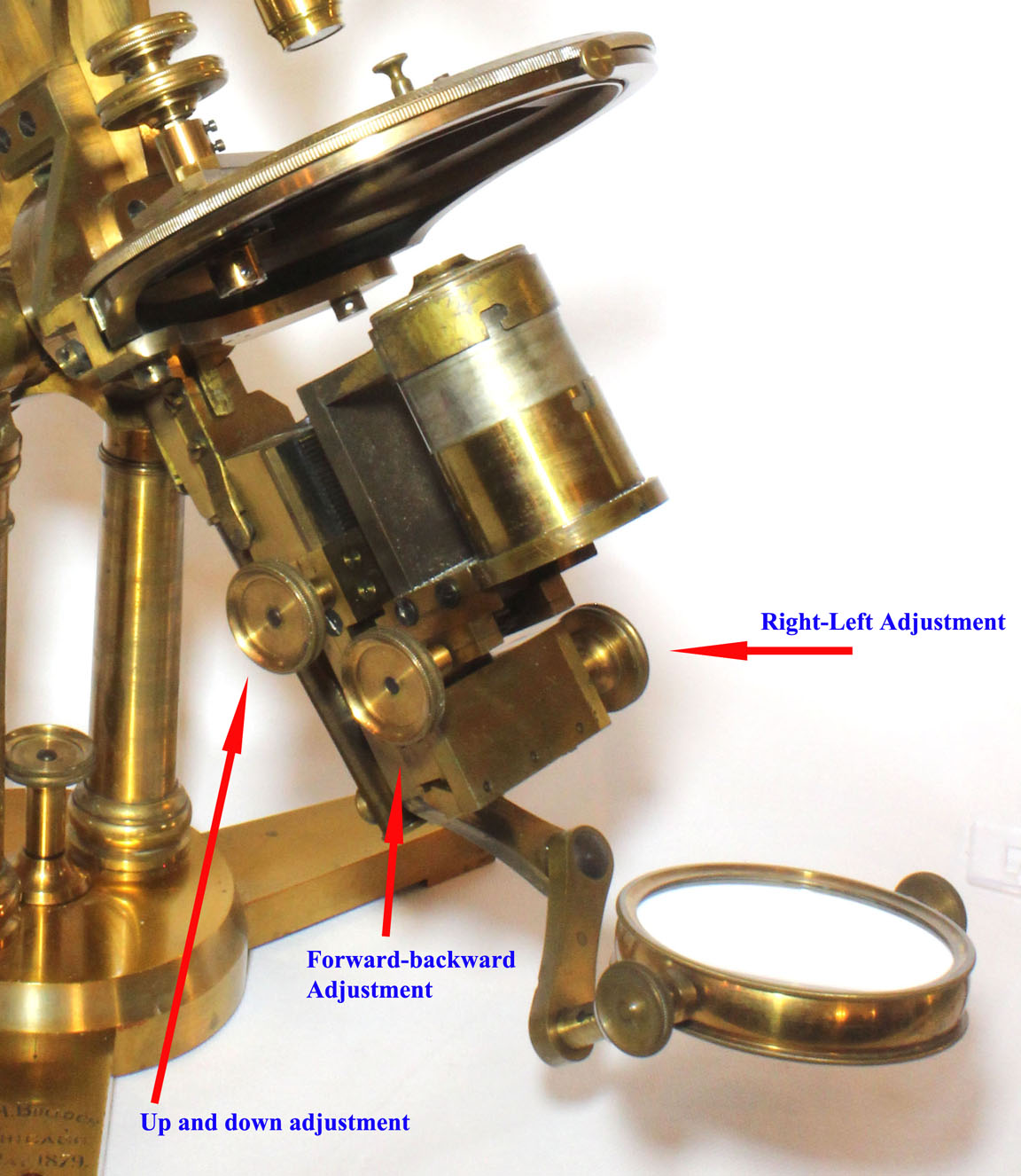
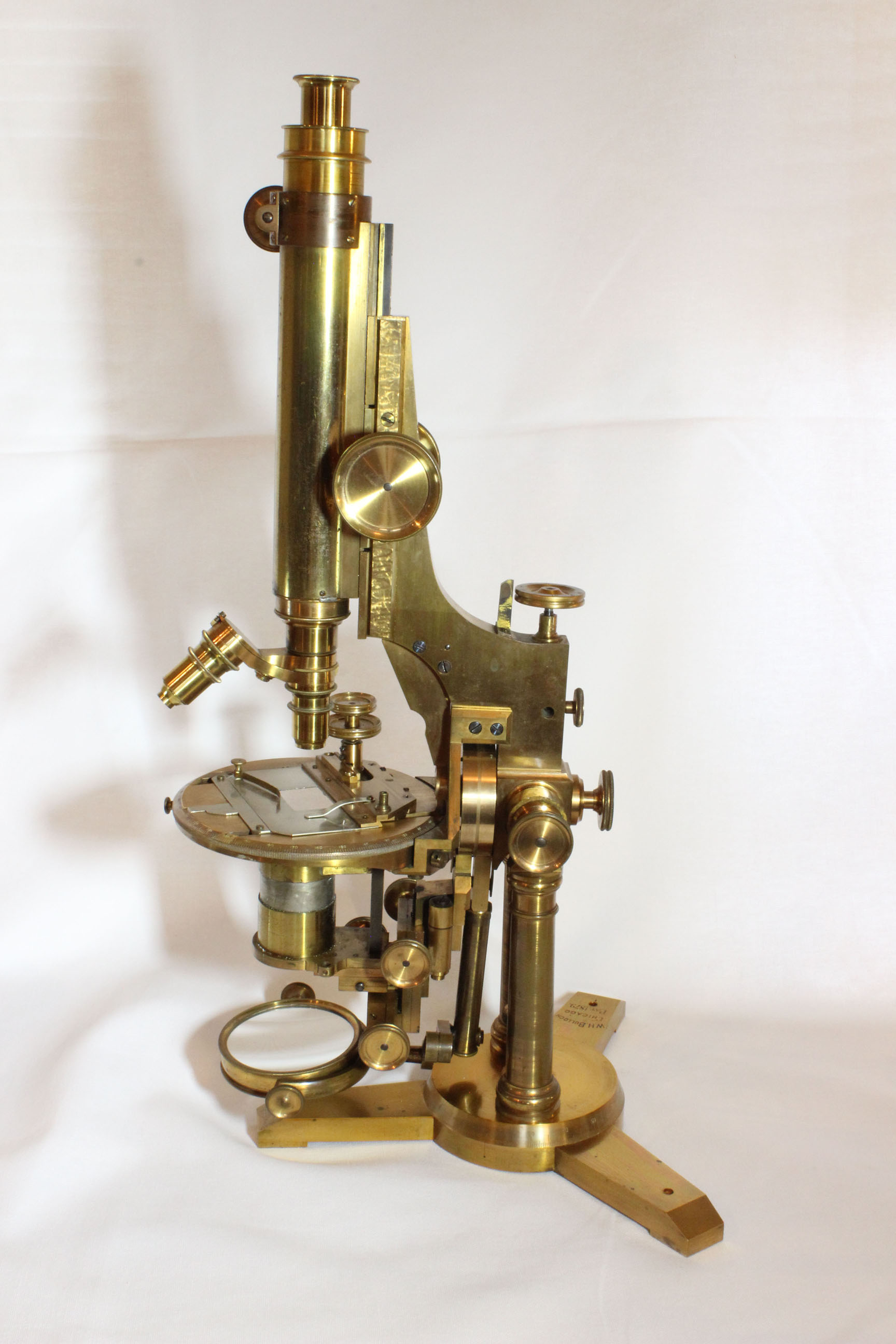
 The substage can be raised or lowered by straight rack and pinion. The
condenser support rings can be centered (or decentered), via a rack and pinion adjustment
for the front and back directions and a worm screw for the right-left movement; each of these is controlled by knurled knobs. There is a provision to swing the entire condenser assembly out of the optical axis via a vertically oriented hinge; a sprung click-stop holds it in the normal position. There is a separate calibrated swinging tailpiece for the mirror and a separate calibrated swinging
tailpiece for the substage, each with silvered scales. Although each of
the tailpieces have independent rotation, there is a click stop to
allow both tailpieces to rotate together, and two stops for the
vertical
position, one in front of the front-most tailpiece(with condenser fitting), and one in back
of the rear (mirror supporting) tailpiece. The clickstop which serves to keep the
two tailpieces together (when desired) protrudes from the front
tailpiece and registers on a slotted screw on the front side of the back tailpiece.
The substage can be raised or lowered by straight rack and pinion. The
condenser support rings can be centered (or decentered), via a rack and pinion adjustment
for the front and back directions and a worm screw for the right-left movement; each of these is controlled by knurled knobs. There is a provision to swing the entire condenser assembly out of the optical axis via a vertically oriented hinge; a sprung click-stop holds it in the normal position. There is a separate calibrated swinging tailpiece for the mirror and a separate calibrated swinging
tailpiece for the substage, each with silvered scales. Although each of
the tailpieces have independent rotation, there is a click stop to
allow both tailpieces to rotate together, and two stops for the
vertical
position, one in front of the front-most tailpiece(with condenser fitting), and one in back
of the rear (mirror supporting) tailpiece. The clickstop which serves to keep the
two tailpieces together (when desired) protrudes from the front
tailpiece and registers on a slotted screw on the front side of the back tailpiece.
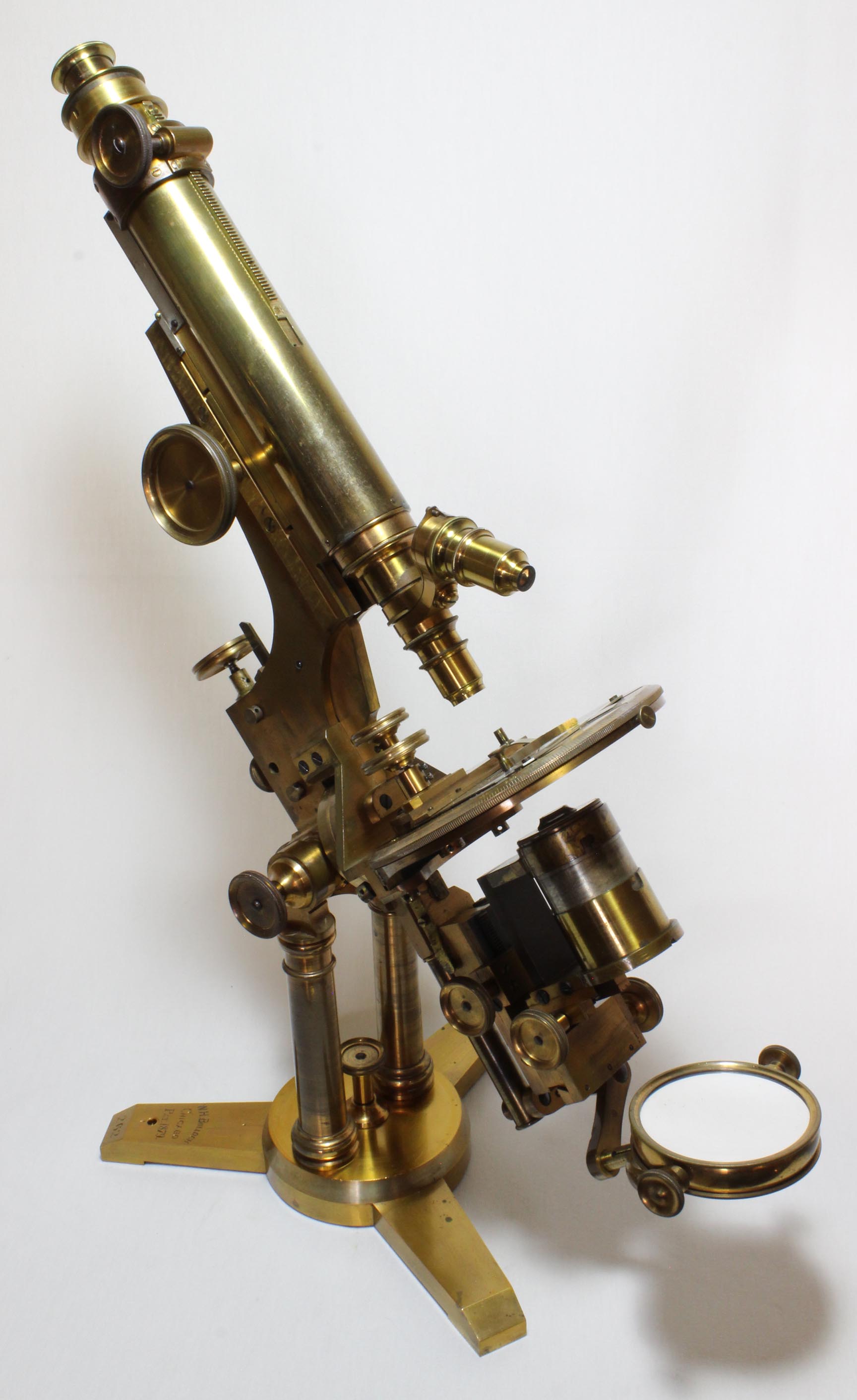
The planoconcave mirror is
three inches in diameter. The
gimbaled mirror can rotate to above the stage for use in top lighting and is attached to the tailpiece by 2 articulating pieces of brass.
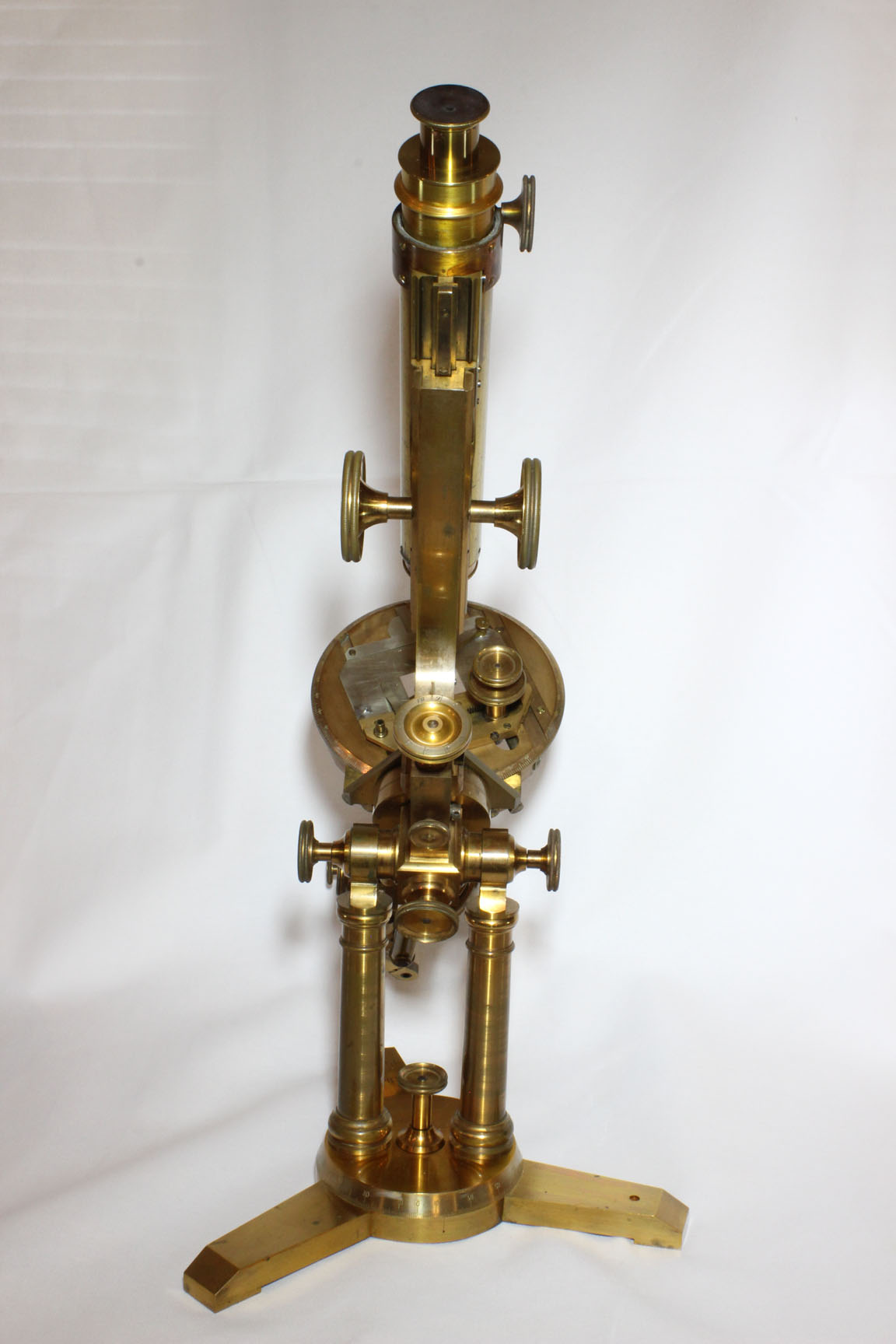
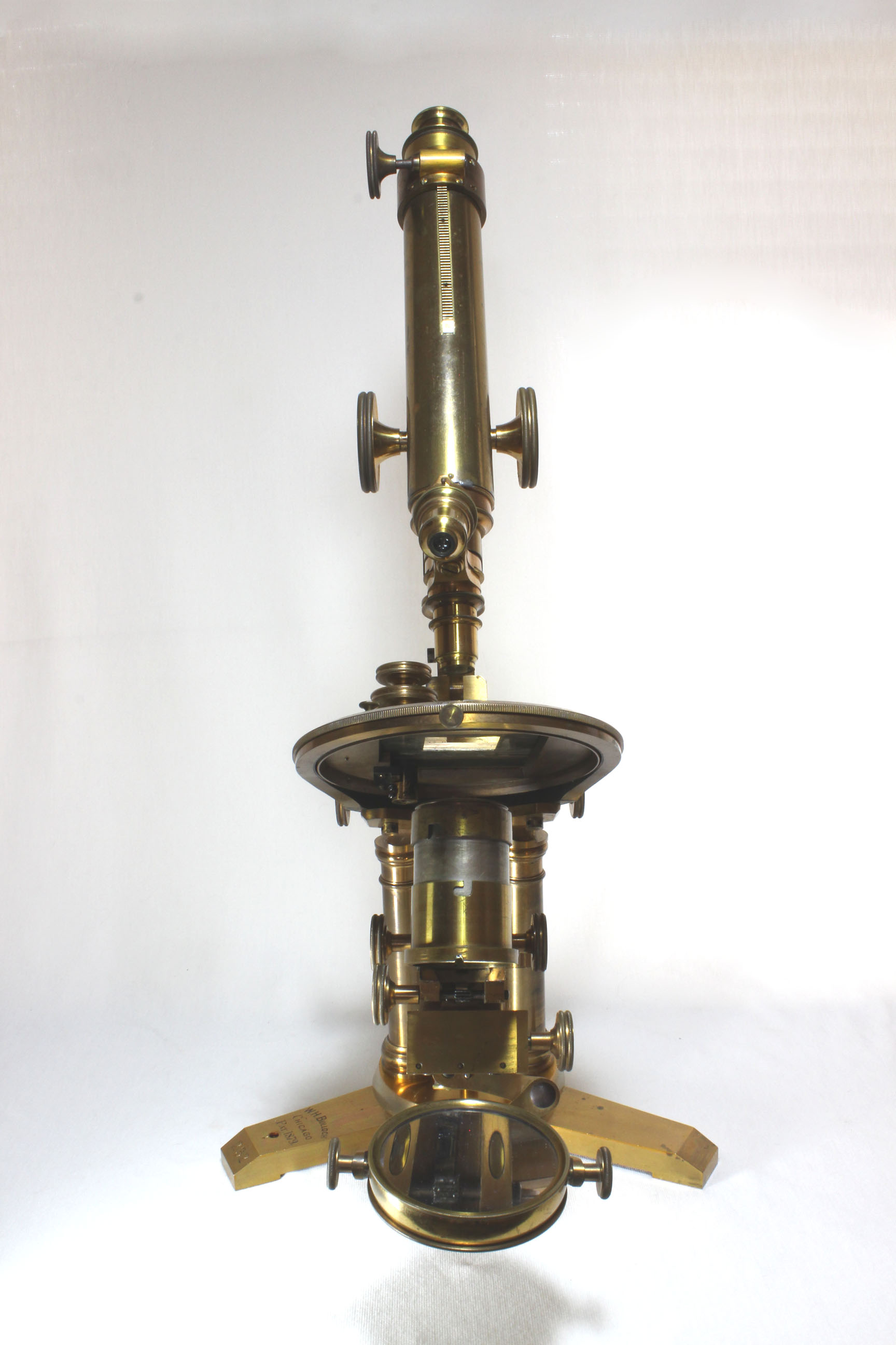
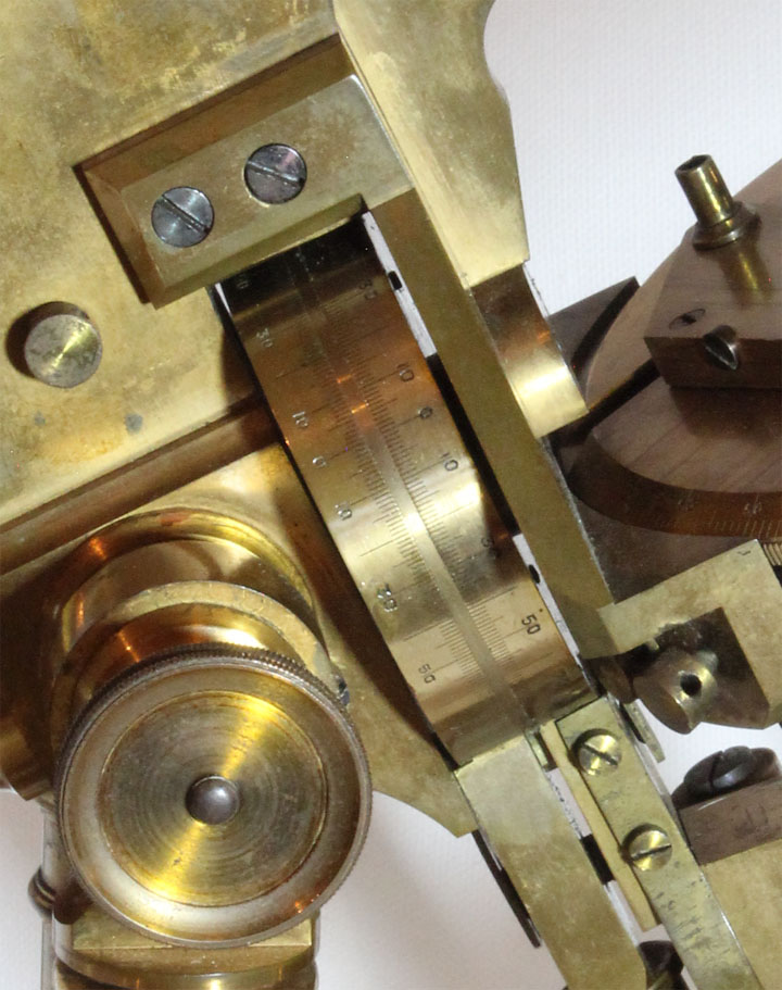
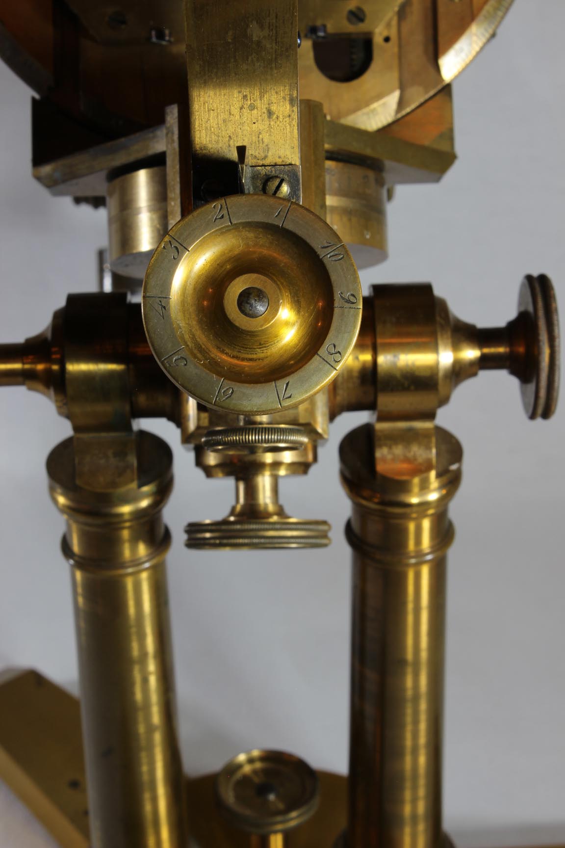
 The five and one half inch diameter mechanical stage is
controlled through concentric knurled knobs projecting
vertically, which allows the stage to fully rotate 360 degrees, without the controls colliding with the limb. Both the X and Y adjustments of this stage are by rack and pinion. This
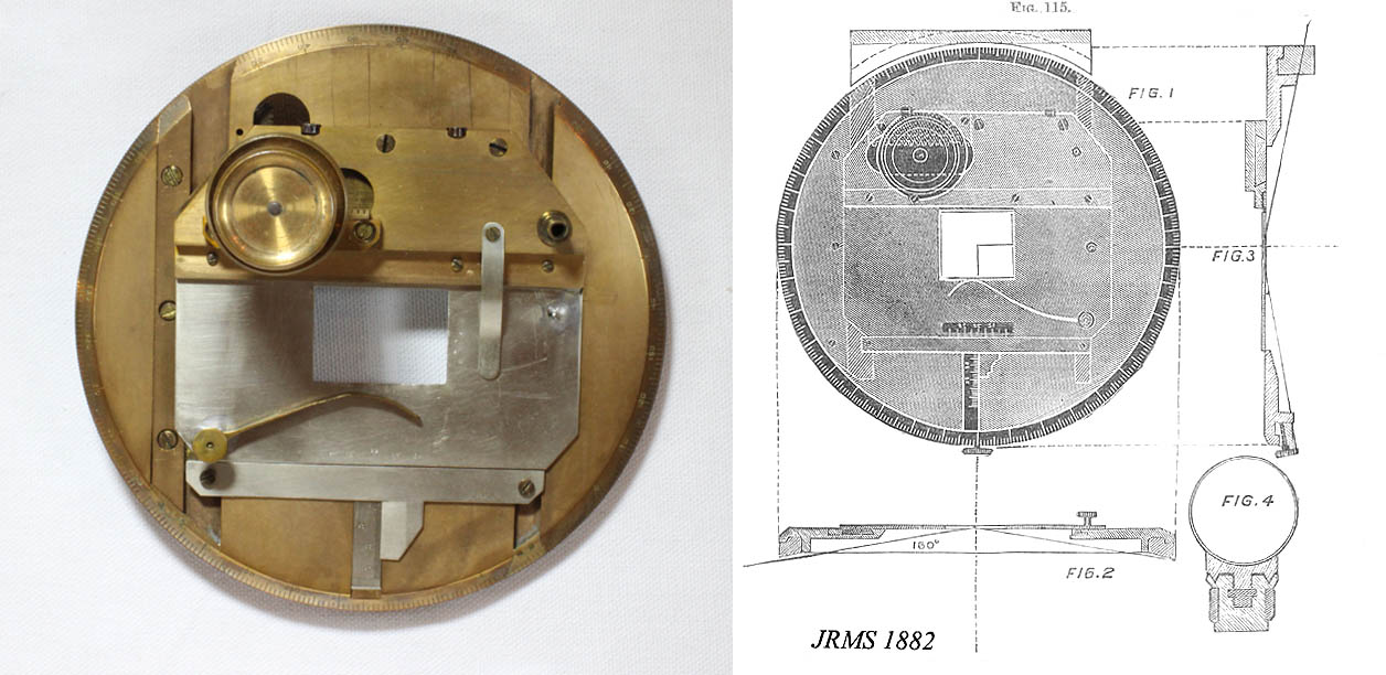
stage is on the plan as published in the JRMS in 1882. A disadvantage of this type of control, is that when a double or triple nosepiece is used, as the stage is rotated, the knobs could collide with the objective(s) not in use. Bulloch partly solved this problem by designing a triple nosepiece that angled the rotation of the objectives in such a way that the objectives not in use were oriented more towards the horizontal, raising their ends further away from the stage. A small knurled knob in the front of the stage support ring allows adjustment of tension on the rotational movement or locking it in position. The beveled edge of the rotating mechanical stage is silvered and calibrated 0-360 degrees in one degree intervals, labelled every ten degrees. There is a nickel-plated pointer to register the degrees of rotation on the right side of the stage near the saddle. Centering of the stage is possible through fittings near the rear on each side. The stage has finely divided scales in the X and Y directions, divided in very tiny intervals (0-50) labelled every ten intervals. There is a pin stop for
the edge of the slide. The left stage clip holds the slide down, while
the one on the right is adjusted to hold the slide back against the
ledge; a small knob is provided for adjusting the right sided stage
clip. The metal scales and stage supporting plate are nickel-plated.
There is a fitting for a stage forceps or other accessory on the left
side of the mechanical stage.
The five and one half inch diameter mechanical stage is
controlled through concentric knurled knobs projecting
vertically, which allows the stage to fully rotate 360 degrees, without the controls colliding with the limb. Both the X and Y adjustments of this stage are by rack and pinion. This
stage is on the plan as published in the JRMS in 1882. A disadvantage of this type of control, is that when a double or triple nosepiece is used, as the stage is rotated, the knobs could collide with the objective(s) not in use. Bulloch partly solved this problem by designing a triple nosepiece that angled the rotation of the objectives in such a way that the objectives not in use were oriented more towards the horizontal, raising their ends further away from the stage. A small knurled knob in the front of the stage support ring allows adjustment of tension on the rotational movement or locking it in position. The beveled edge of the rotating mechanical stage is silvered and calibrated 0-360 degrees in one degree intervals, labelled every ten degrees. There is a nickel-plated pointer to register the degrees of rotation on the right side of the stage near the saddle. Centering of the stage is possible through fittings near the rear on each side. The stage has finely divided scales in the X and Y directions, divided in very tiny intervals (0-50) labelled every ten intervals. There is a pin stop for
the edge of the slide. The left stage clip holds the slide down, while
the one on the right is adjusted to hold the slide back against the
ledge; a small knob is provided for adjusting the right sided stage
clip. The metal scales and stage supporting plate are nickel-plated.
There is a fitting for a stage forceps or other accessory on the left
side of the mechanical stage.
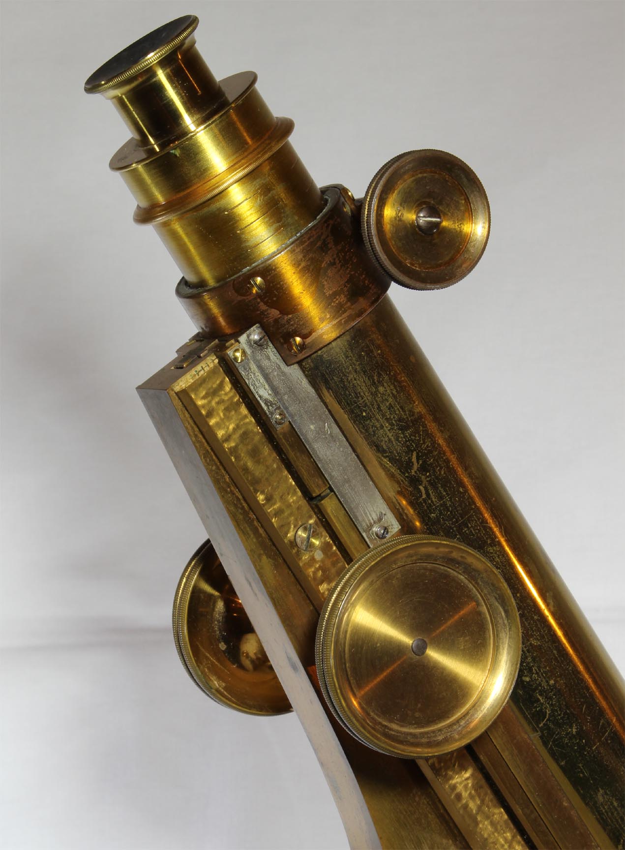 There is a damascened finish to the limb in the area
supporting the optical tube. There is a finely divided nickel-plated scale attached to the top portion of the main optical tube on the right side which is calibrated 0 to 2 inches in 1/8 inch intervals and on the same scale also in centimeters and millimeters. There is a matching but unsigned double
nosepiece. The bottom tube fitting which houses the threads for the objective (or double objective changer), has been repaired, soldered into position at the end of the tube in three places.
There is a damascened finish to the limb in the area
supporting the optical tube. There is a finely divided nickel-plated scale attached to the top portion of the main optical tube on the right side which is calibrated 0 to 2 inches in 1/8 inch intervals and on the same scale also in centimeters and millimeters. There is a matching but unsigned double
nosepiece. The bottom tube fitting which houses the threads for the objective (or double objective changer), has been repaired, soldered into position at the end of the tube in three places.
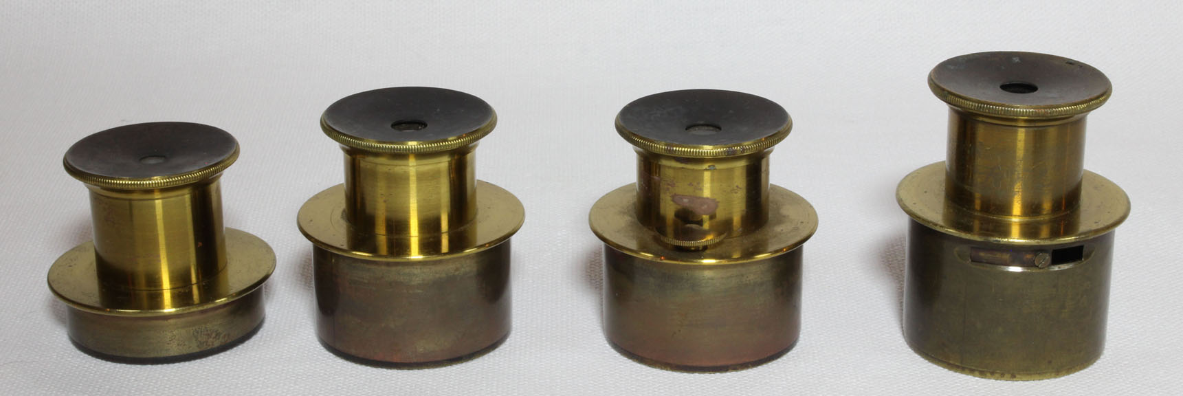
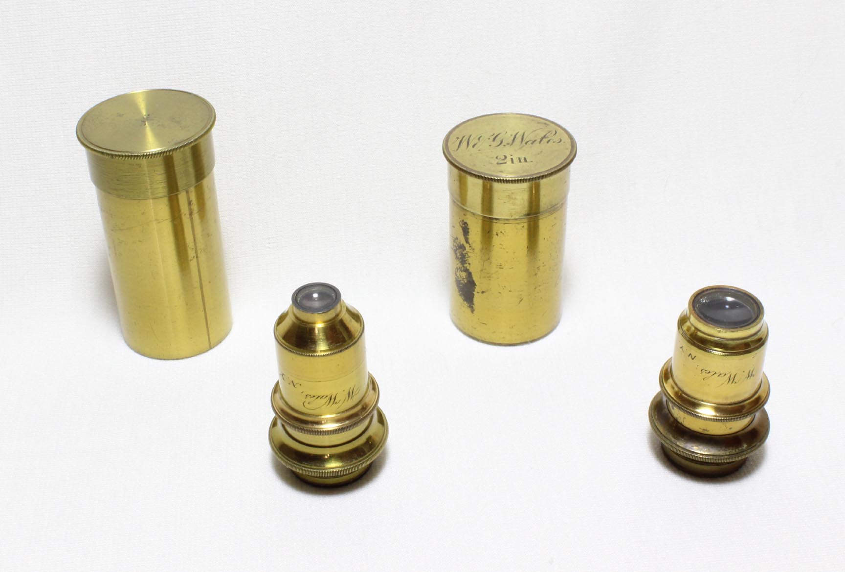 Two fine William Wales objectives are present. One is a 1 1/2 inch focal length signed 'W. Wales, N.Y., 1/1/2' housed in a can signed 'W. & G. Wales 2 in., The other objective is also signed 'W. Wales, N. Y.' and although it does not have its focal length inscribed on it. I would estimate its focal length is about a 2/3 inch. Its can is
unsigned except for a focal length listed as '2/3.'
Two fine William Wales objectives are present. One is a 1 1/2 inch focal length signed 'W. Wales, N.Y., 1/1/2' housed in a can signed 'W. & G. Wales 2 in., The other objective is also signed 'W. Wales, N. Y.' and although it does not have its focal length inscribed on it. I would estimate its focal length is about a 2/3 inch. Its can is
unsigned except for a focal length listed as '2/3.'
 Coarse focus is by straight rack and pinion, fine by long
lever controlled by a silver-scaled knurled knob with fine threaded screw. The fine focus knob is calibrated in 1/1000 inch intervals and has a groove in which a cord could have been placed for 'remote control' of focus during photography, which in those days required a large apparatus. There are calibrations on the drawtube which is calibrated from 1 to 12 cm in half centimeter intervals, with numbers engraved for each cm. It is also calibrated from 1 to 5 inches in quarter inch intervals and is numbered
at each whole inch. The drawtube is controlled via rack and pinion, and although the original rack was missing, it has been replaced with a rack contemporary to the microscope. It is notable that as the drawtube is raised, eventually a slot, which accomodates the rack when it is in the down position, opens to expose the inside of the tube. This is not a good design as dust and light could enter. This problem was solved on the Watson van Heurcks, which also had a rack and pinion control to the drawtube, by encasing the rack area in a rectangular compartment as in the Grand Van Heurck microscope in this collection.
At the top of the drawtube is a small slot for registering an eyepiece or goniometer.
Coarse focus is by straight rack and pinion, fine by long
lever controlled by a silver-scaled knurled knob with fine threaded screw. The fine focus knob is calibrated in 1/1000 inch intervals and has a groove in which a cord could have been placed for 'remote control' of focus during photography, which in those days required a large apparatus. There are calibrations on the drawtube which is calibrated from 1 to 12 cm in half centimeter intervals, with numbers engraved for each cm. It is also calibrated from 1 to 5 inches in quarter inch intervals and is numbered
at each whole inch. The drawtube is controlled via rack and pinion, and although the original rack was missing, it has been replaced with a rack contemporary to the microscope. It is notable that as the drawtube is raised, eventually a slot, which accomodates the rack when it is in the down position, opens to expose the inside of the tube. This is not a good design as dust and light could enter. This problem was solved on the Watson van Heurcks, which also had a rack and pinion control to the drawtube, by encasing the rack area in a rectangular compartment as in the Grand Van Heurck microscope in this collection.
At the top of the drawtube is a small slot for registering an eyepiece or goniometer.
 There are four eyepieces, one of
which has a movable pointer, and one of which has a slot with a window that opens and closes to admit, e.g. an eyepiece micrometer. The pointer eyepiece is otherwise identical to another of the four, so there are only three different magnifications.
There are four eyepieces, one of
which has a movable pointer, and one of which has a slot with a window that opens and closes to admit, e.g. an eyepiece micrometer. The pointer eyepiece is otherwise identical to another of the four, so there are only three different magnifications.
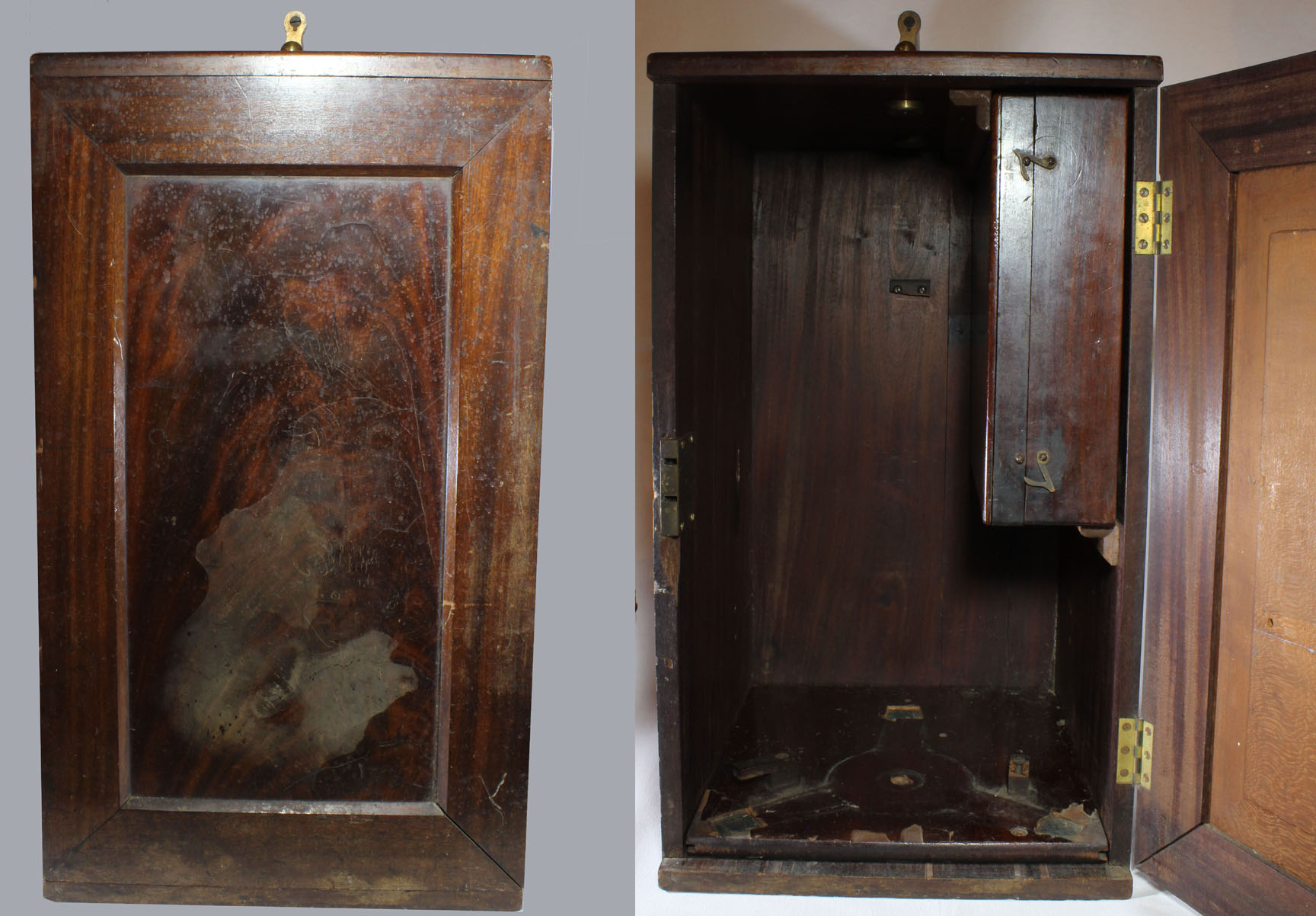 The stand without the case weighs over twenty one pounds. The large hardwood case has a brass handle on top and a lock for the door, although the key is missing. The accessory box slides into the cabinet, but lacks its insert and additional accessories. The accessory case still has impressions on the bottom of many objective cans that must have previously been with the instrument. As with many other Bulloch microscopes, there is a sliding wooden base which has three cutouts for the foot of the microscope and this base can slide out of the case; it has grooves on its sides which originally fit into guides fitted to the bottom of the case, now gone.
HISTORY OF THE BULLOCH CONGRESS MICROSCOPES
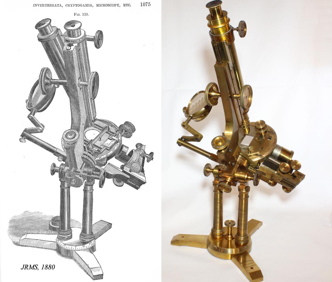 This is the improved, but not the last version, of the Congress stand. An engraving of the previous version was published in the Journal of the Royal Microscopical Society (JRMS) in 1880; my stand is shown in the same position as the engraving from 1880. Note that the knob to fix the position the rotation of the foot was not provided on that version, and that it had the earlier version of mechanical stage.
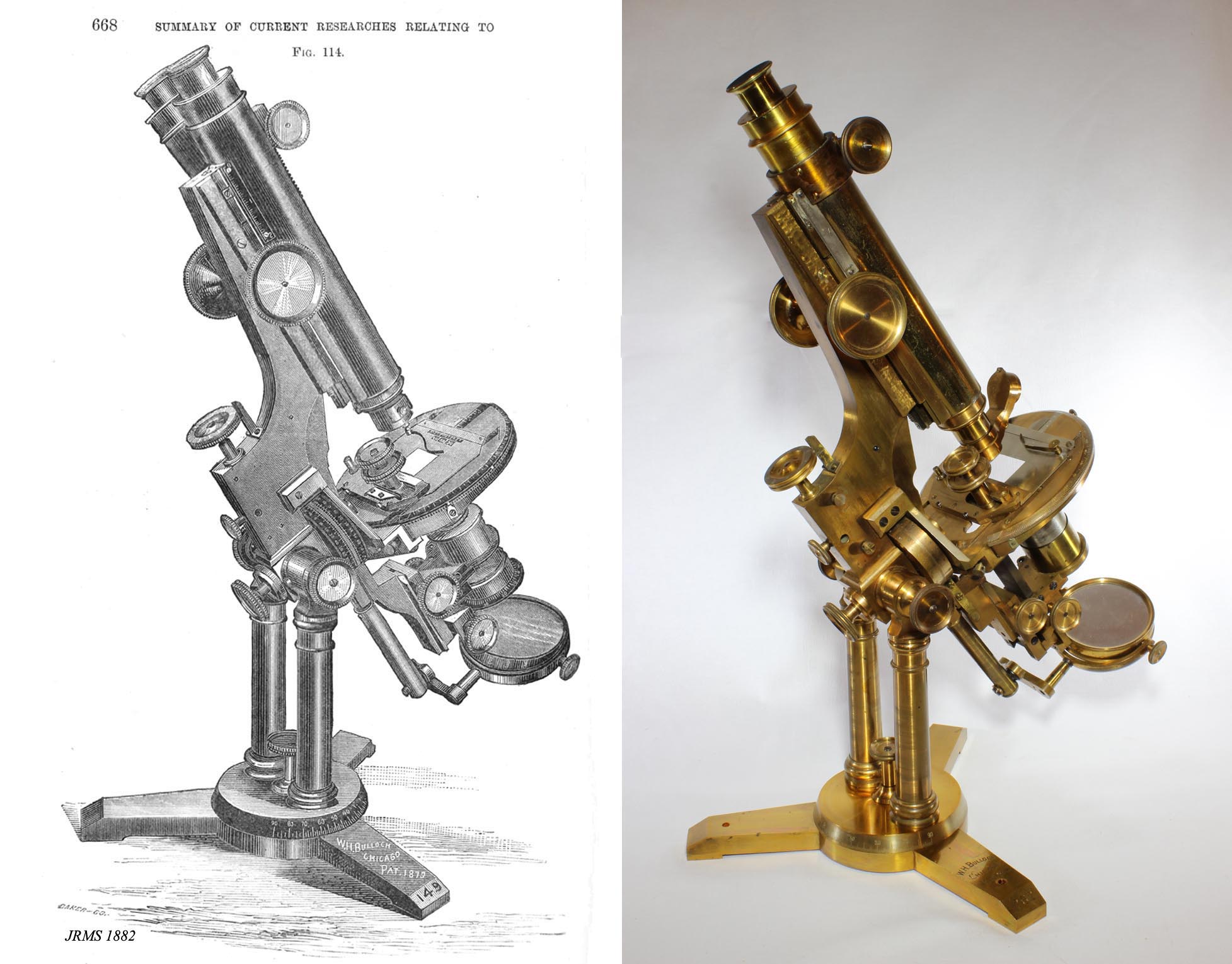 In 1882, an engraving of this version was published in the JRMS. Although the calibrated revolving base could be used to measure numerical aperture, its purpose as described by Bulloch was as a convenience for photography. This microscope was sold in both monocular and binocular versions.
Walter H. Bulloch was born in Scotland and emigrated with his parents to New York as a teenager. He was soon apprenticed to Benjamin Pike and
Sons where he learned the art of fine machining (and apparently
microscope design). He soon joined in partnership with the famous objective maker William Wales, who made objectives, selling his stands with Wales objectives, but eventually moved to Chicago in 1866. Despite the apparent work with Wales, stands by Bulloch from that time, before his move to Chicago, have not yet been identified. Although he initially prospered in Chicago, the Great Chicago Fire of 1871 destroyed his premises and he never completely recovered from this loss. To the best of my knowledge, microscopes dating from this early period in Chicago have also not been firmly identified. Following the 1871 fire he left Chicago and went to Boston to work with the famous Robert B Tolles, inventor of the oil-immersion objective. He was back in business in Chicago by 1872, and stands dating from about 1875 have been identified. As is evidenced by a signature on stand number 77, his agent in Chicago in that era was
T. F. Nelson. T.F. Nelson apparently declared Bankruptcy in 1879
according to the Chicago Daily Law Bulletin, volume 25. I have not seen another stand with the Nelson reference.
A 1879 patent is for features of his design used on the Professional, Biological, and 'A1' Congress stands. His design for the Congress stand was also published in the Journal of the Royal Microscopical Society in 1880 and the improved version, the one seen on this web page, starting about 1882.
In 1889 he again left Chicago for a brief time working for
the U.S. Geodetic Survey as part of the Bureau of weights and measures but he again returned to Chicago after only six months with the Survey group. In 1890 he opened business again in Chicago, but had longstanding bad health and died in November of 1891. For a few months after his death, a M. Von Mehren 'took over' his business but his entire business was shortly then taken over by the 'opticians' E.B. Meyrowitz
of New York City, (who were already his agents long before his death), and
several surviving instruments have the Meyerowitz signature on the foot.
As noted above, there is no record known to the author of Bulloch ever
making his own objectives. However Bulloch made impressive stands,
especially his Congress stand, the Professional, Lithological, and the Biological Number 2.
Bulloch made relatively few stands compared to many other well-known
makers. This is in part due to the limited time he was in business, and
the fact that he was a perfectionist. Anyone who has had the privilege
of handling Bulloch instruments cannot help but admire his quality of
workmanship and his very sound designs. One will also be impressed in that almost no two are exactly alike
Bulloch was constantly improving his stands and the Congress evolution page describes these changes for this model.
For a tabular listing of Bulloch's locations and activities see the Bulloch Chronology Page. A page devoted to all the different Bulloch microscope models and their evolution illustrated with both engravings and actual examples is now available on this site.
This
microscope, originally part of the Sam Koslov collection, was purchased
at auction in late 1998. During a difficult time, it had to be sold.
The author is indebted to Dr Stuart Warter, former Chairman of Biology
at the University of California, Long Beach, for being the custodian of
this microscope for more than a decade, and kindly allowing me to buy
it back from him in December 2014. I will always be in his debt for
this kindness.