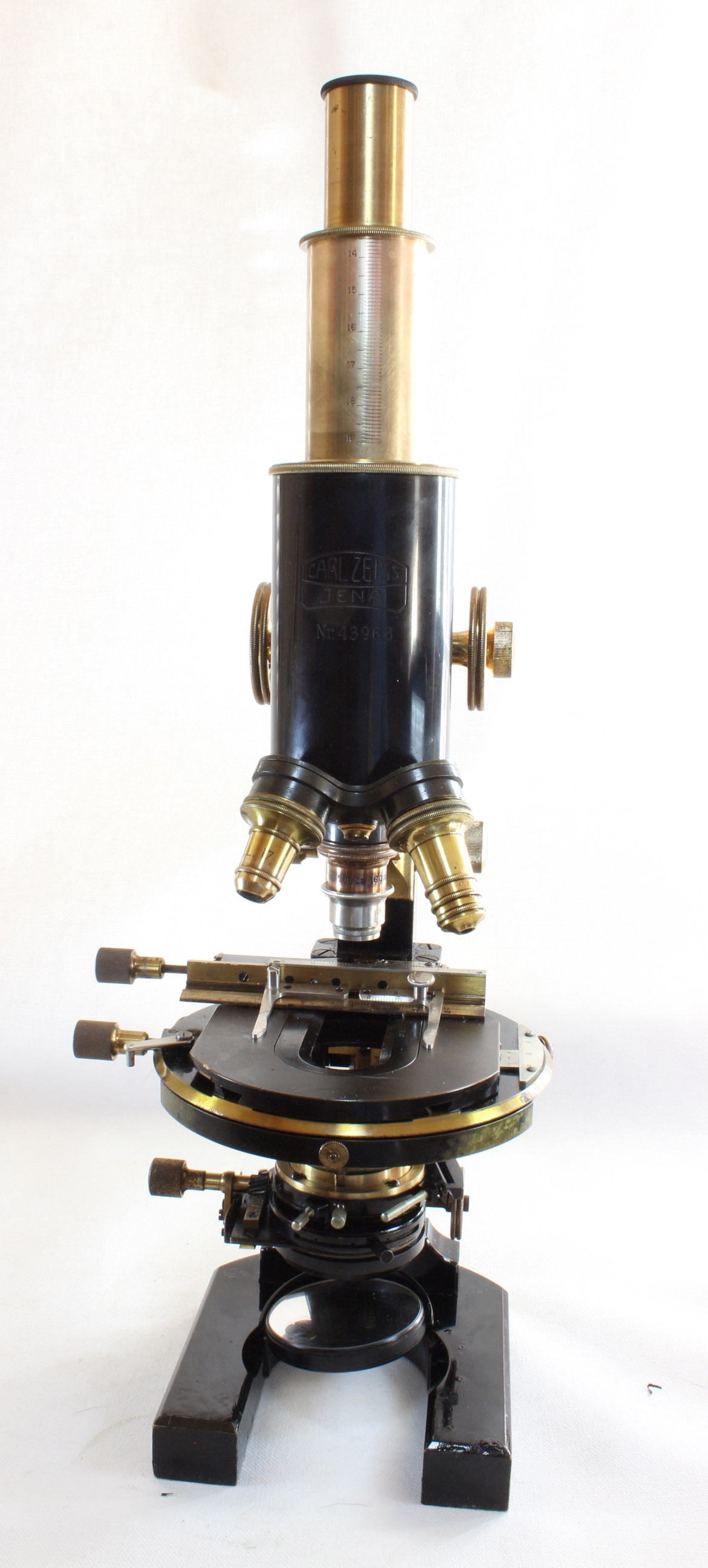
Carl Zeiss, Jena
| DESCRIPTION | HISTORY |
Please Click On Any Picture for a Larger Version
 It was offered
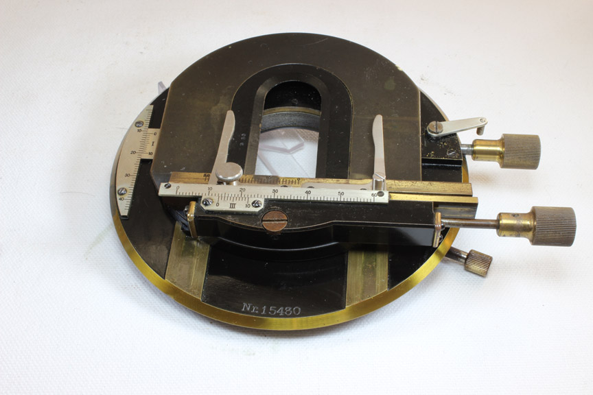
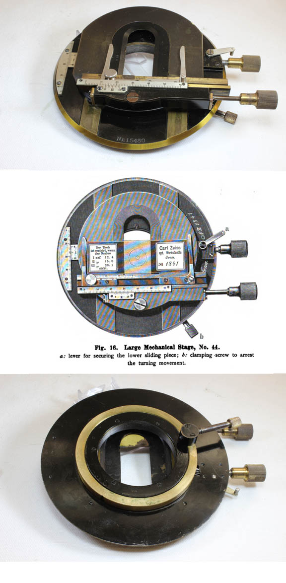
with options of three different stages, this example being equipped with
the 'Large Mechanical Stage, No. 44.' shown to the right. The stage has vernier scale graduations in both X and Y axes.
A third scale and vernier was added for recording the position of the movable 'check-piece' or slide holder,
which secures the position of the left side of the slide. The right side slide holder also slides in the same groove.
This allows the X and Y verniers to then be used as a 'finder' to locate a
specific spot on the slide repeatedly. This stage also has rotational motion, with a locking screw knob.
The rotating stage also has two centering screws with milled knobs.
There is also a small lever to lock the
mechanical stage forward and backward motion, a feature especially useful when the stand is inclined or even horizontal.
Another stage, the 'Photomicrographic Stage' (also shown for comparison on the
Zeiss Stage Page)
was also offered as an option; this stage had a different kind of adjustment which
assumed gross positioning of the slide by hand, and then only a fine adjustment via controls to allow the object to be
carefully positioned for photography. This stand could also be provided with a rotating, but otherwise plain vulcanite
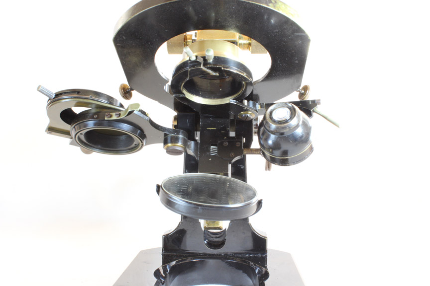
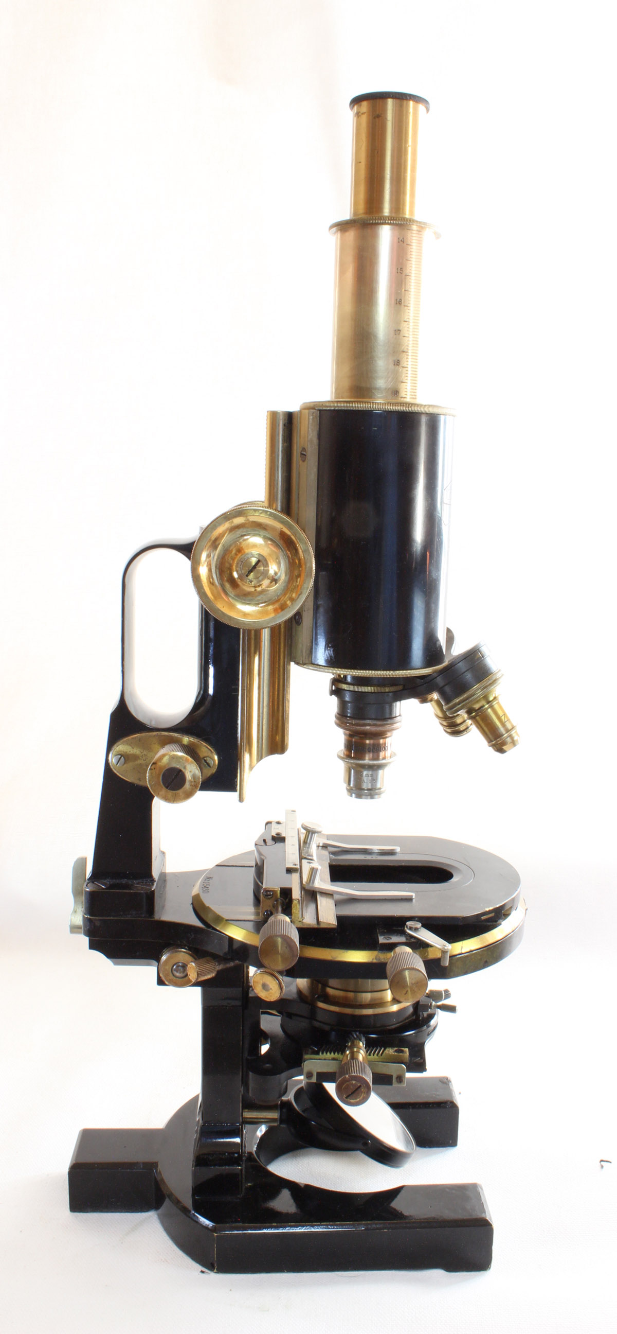
stage with stage clips. The substage has diagonal rack and pinion height adjustment. This example is equipped with
the Abbe Swing-out Condenser, a plain condenser also being offered. The condenser apparatus currently on this microscope
has only one iris diaphragm, below the condenser fitting. This iris can rotate, and via a small diagonal rack and pinion,
be offset from center to allow variations in indirect illumination. The iris and the optical component (condenser) can be
swung out of the optical axis separately as desired. The fitting that holds the condenser then remains in place to accept
other accessories as desired.
It was offered
with options of three different stages, this example being equipped with
the 'Large Mechanical Stage, No. 44.' shown to the right. The stage has vernier scale graduations in both X and Y axes.
A third scale and vernier was added for recording the position of the movable 'check-piece' or slide holder,
which secures the position of the left side of the slide. The right side slide holder also slides in the same groove.
This allows the X and Y verniers to then be used as a 'finder' to locate a
specific spot on the slide repeatedly. This stage also has rotational motion, with a locking screw knob.
The rotating stage also has two centering screws with milled knobs.
There is also a small lever to lock the
mechanical stage forward and backward motion, a feature especially useful when the stand is inclined or even horizontal.
Another stage, the 'Photomicrographic Stage' (also shown for comparison on the
Zeiss Stage Page)
was also offered as an option; this stage had a different kind of adjustment which
assumed gross positioning of the slide by hand, and then only a fine adjustment via controls to allow the object to be
carefully positioned for photography. This stand could also be provided with a rotating, but otherwise plain vulcanite
stage with stage clips. The substage has diagonal rack and pinion height adjustment. This example is equipped with
the Abbe Swing-out Condenser, a plain condenser also being offered. The condenser apparatus currently on this microscope
has only one iris diaphragm, below the condenser fitting. This iris can rotate, and via a small diagonal rack and pinion,
be offset from center to allow variations in indirect illumination. The iris and the optical component (condenser) can be
swung out of the optical axis separately as desired. The fitting that holds the condenser then remains in place to accept
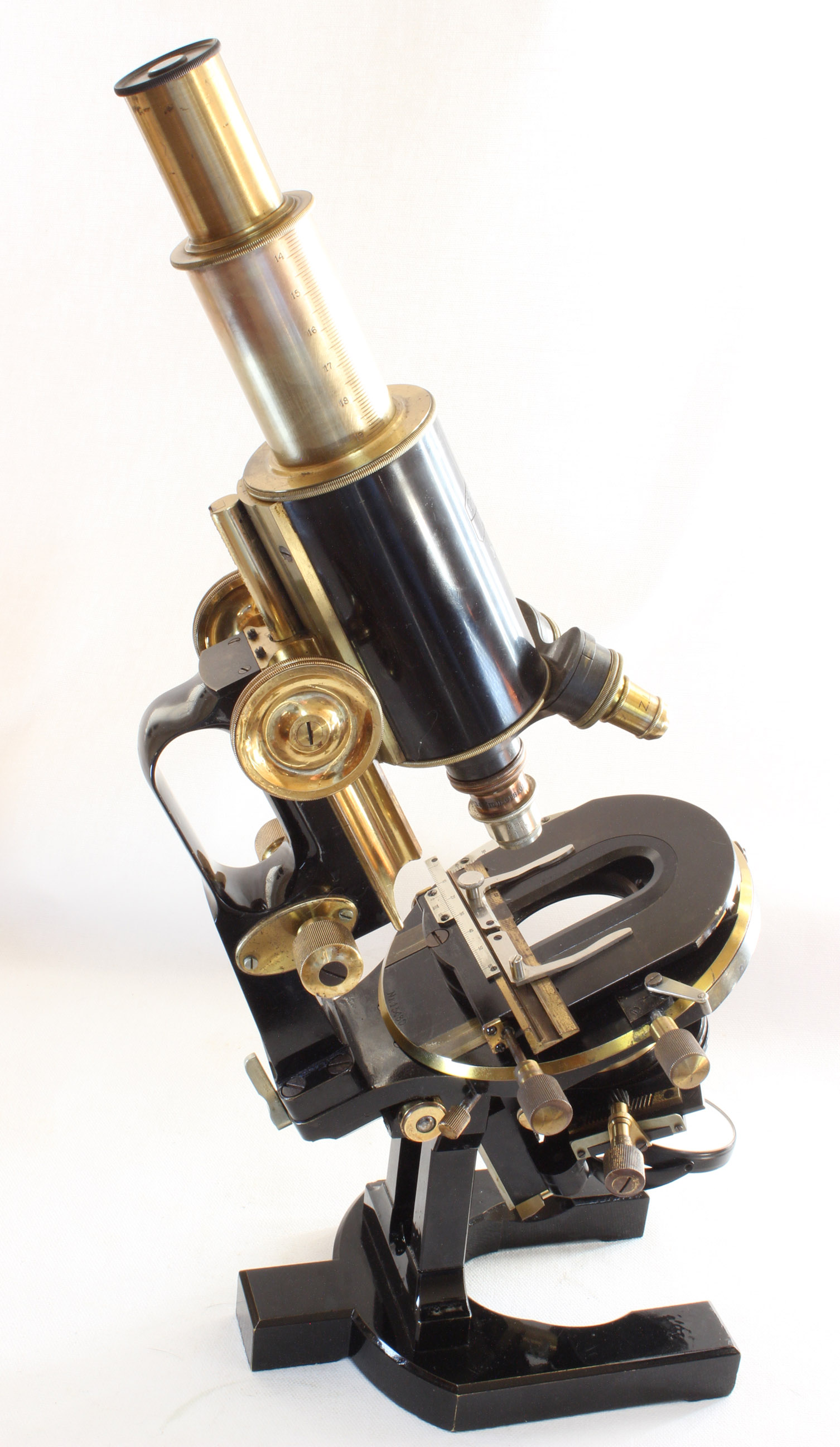
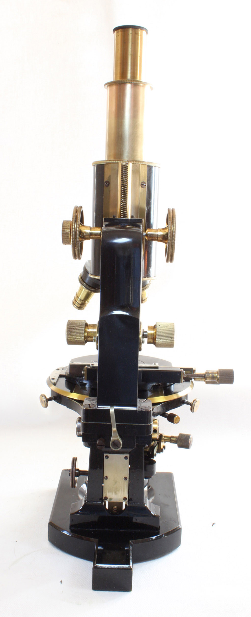
other accessories as desired.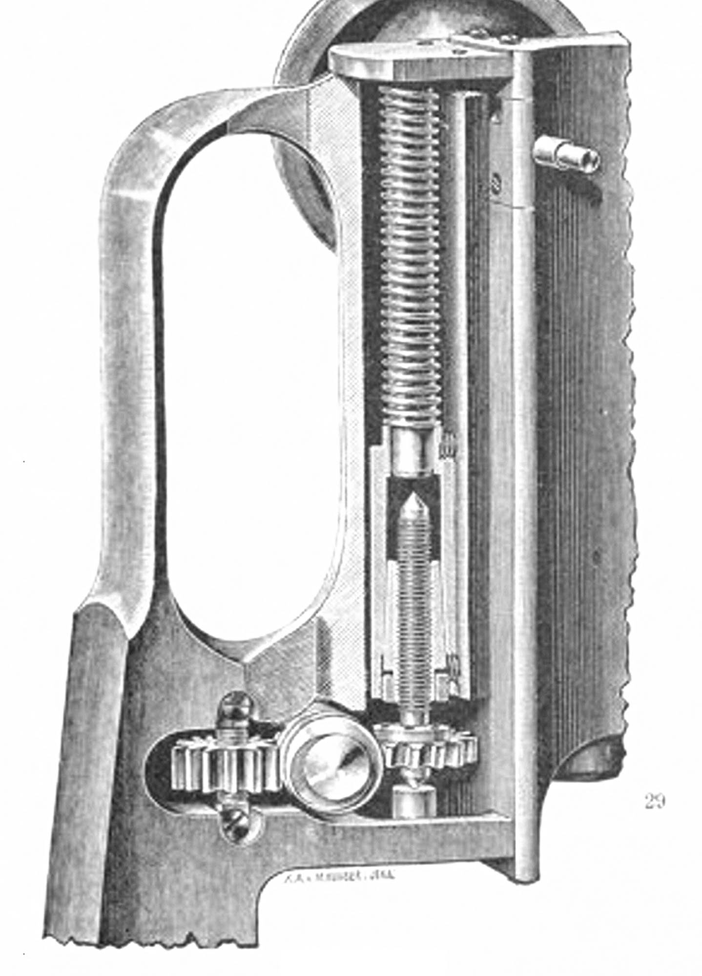 This microscope was the first model (when it was called the 1c) to feature the Berger side-fine-adjustment mechanism.
Max Berger described this device, the first good side fine adjustment made, in 1898 in the
Zeitschrift fur Instrumentenkunde, vol. XVIII, 1898, pp. 129-133
This fine adjustment has advantages over prior designs of, while allowing adjustment from the side of the stand, it at the same time provided a low-friction and very fine control to the fine adjusment.
It makes use of a fine screw, the end of which is attached to a gear; turning the knob turns a worm gear, which in turn activates the gear, and precisely turns the long screw. This method
imparted a much finer control than a simple knob on the screw, as was the usual standard earlier. Another gear turning in an opposite direction, and engaging the
same wormgear, is on the back side of the worm. The purpose of this gear was to limit the travel of the fine adjustment.
To limit the fine adjustment, this gear, much wider than the one turning the focusing screw, is threaded and rides a fixed screw to rise or fall inside the stand until it reaches a limit to prevent the fine adjustment travel from being excessive. Backlash is prevented by a powerful spring holding the tube support down on the fine adjusting screw.
The Zeiss catalog states that whereas the divisions on the milled knob of the older type of adjustment represented 0.005 mm of travel, the Berger knob divisions equalled 0.002 mm, less than half of that distance. By extrapolation, and knowing the refractive index of the object, an approximation of thickness of objects or coverslips could be made.
This microscope was the first model (when it was called the 1c) to feature the Berger side-fine-adjustment mechanism.
Max Berger described this device, the first good side fine adjustment made, in 1898 in the
Zeitschrift fur Instrumentenkunde, vol. XVIII, 1898, pp. 129-133
This fine adjustment has advantages over prior designs of, while allowing adjustment from the side of the stand, it at the same time provided a low-friction and very fine control to the fine adjusment.
It makes use of a fine screw, the end of which is attached to a gear; turning the knob turns a worm gear, which in turn activates the gear, and precisely turns the long screw. This method
imparted a much finer control than a simple knob on the screw, as was the usual standard earlier. Another gear turning in an opposite direction, and engaging the
same wormgear, is on the back side of the worm. The purpose of this gear was to limit the travel of the fine adjustment.
To limit the fine adjustment, this gear, much wider than the one turning the focusing screw, is threaded and rides a fixed screw to rise or fall inside the stand until it reaches a limit to prevent the fine adjustment travel from being excessive. Backlash is prevented by a powerful spring holding the tube support down on the fine adjusting screw.
The Zeiss catalog states that whereas the divisions on the milled knob of the older type of adjustment represented 0.005 mm of travel, the Berger knob divisions equalled 0.002 mm, less than half of that distance. By extrapolation, and knowing the refractive index of the object, an approximation of thickness of objects or coverslips could be made.
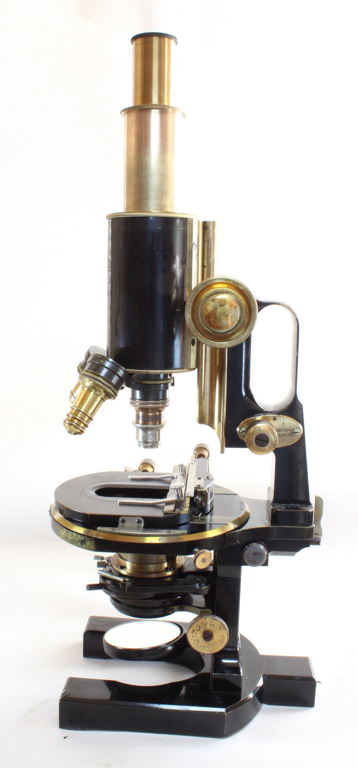
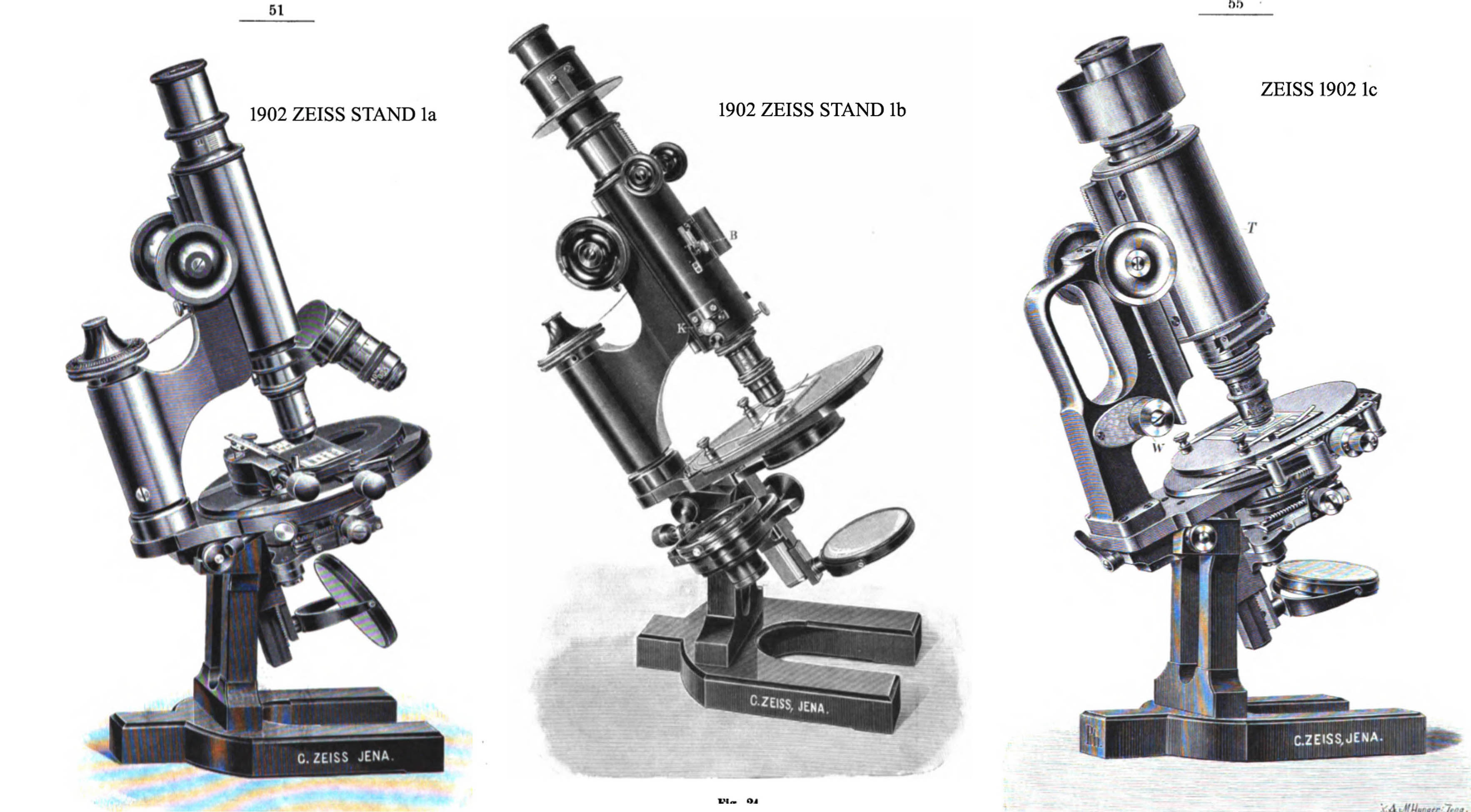 In the 1902 catalog, the three largest stands, designated 1a, 1b and 1c were quite different. As seen here to the left, the 1a and 1b utilized the older directly-adjusted vertical screw for fine adjustment, and the 1b was specifically designed for polarized light work. In additon, these stands, not intended for photography, had the usual narrow main optical tubes. The 1c, on the other hand, featured both the new Berger side-fine-adjustment, and a wider optical tube to facilitate photography; in fact some of these stands have the letters 'Ph'
etched on the back of the foot, which indicated they were for 'photography and projection'.
The 1c, as can be seen in the ad shown to the right,
was promoted as a 'New Photomicrographic Stand.' The 1d in 1902 was the 'Brain Microscope' and had both the wide tube
and Berger fine adjustment and was equipped with a huge stage for studying very large sections.
In the 1902 catalog, the three largest stands, designated 1a, 1b and 1c were quite different. As seen here to the left, the 1a and 1b utilized the older directly-adjusted vertical screw for fine adjustment, and the 1b was specifically designed for polarized light work. In additon, these stands, not intended for photography, had the usual narrow main optical tubes. The 1c, on the other hand, featured both the new Berger side-fine-adjustment, and a wider optical tube to facilitate photography; in fact some of these stands have the letters 'Ph'
etched on the back of the foot, which indicated they were for 'photography and projection'.
The 1c, as can be seen in the ad shown to the right,
was promoted as a 'New Photomicrographic Stand.' The 1d in 1902 was the 'Brain Microscope' and had both the wide tube
and Berger fine adjustment and was equipped with a huge stage for studying very large sections. | YEAR | MODEL NUMBER | ||||||||||||||||||
|---|---|---|---|---|---|---|---|---|---|---|---|---|---|---|---|---|---|---|---|
| 1a | 1b | 1c | 1d | 1e | |||||||||||||||
| TUBE | FINE FOCUS | STAGE | TUBE | FINE FOCUS | STAGE | TUBE | FINE FOCUS | STAGE | TUBE | FINE FOCUS | STAGE | TUBE | FINE FOCUS | STAGE | |||||
| 1902 | NARROW | OLD | PLAIN REVOLVING OR LARGE MECHANICAL | NARROW | OLD | PLAIN REVOLVING OR LARGE MECHANICAL | WIDE | BERGER | PLAIN, OR LARGE MECHANICAL OR PHOTOGRAPHIC | WIDE | BERGER | LARGE PLAIN (BRAIN MICROSCOPE) | ------ | ------ | ------ | ||||
| 1906 | WIDE | BERGER | PLAIN REVOLVING | WIDE | BERGER | LARGE MECHANICAL | WIDE | BERGER | PHOTOGRAPHIC | WIDE | BERGER | PLAIN REVOLVING (& WITH PHOTOACCESSORIES) | WIDE | BERGER | LARGE MECHANICAL (& WITH PHOTOACCESSORIES) |
||||
| 1913 | WIDE | BERGER | PLAIN REVOLVING | WIDE | BERGER | LARGE MECHANICAL | WIDE | BERGER | PHOTOGRAPHIC | --- | ---- | --- | --- | --- | --- | ||||
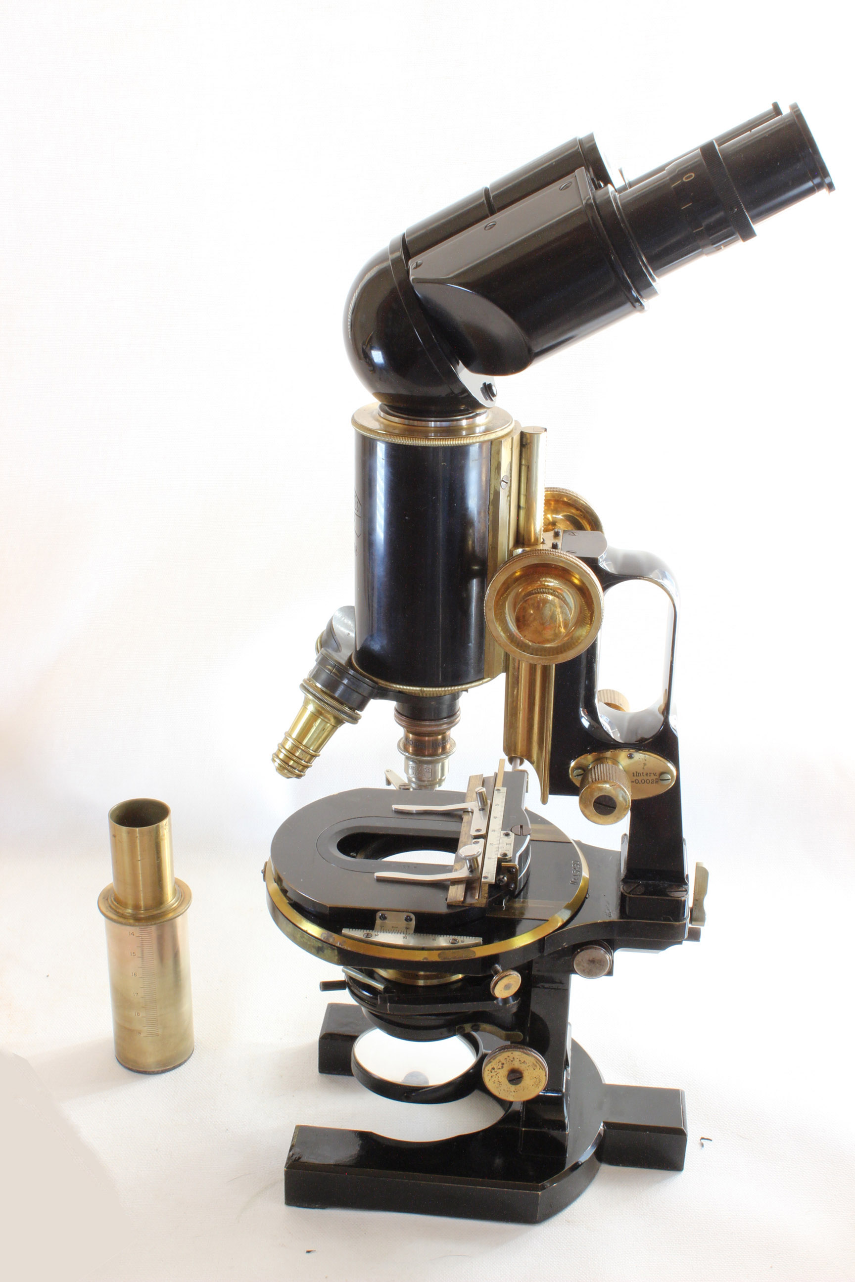 Most binocular heads of the nineteenth and early twentieth centuries effected a change in tube length as the interocular
distance was adjusted. In the 1920's Siedentopf developed a binocular head in which changing the interocular distance
did not result in a change in tube length. This was important at high powers because objectives are designed for specific
tube lengths and distortions are introduced if the tube length is changed. Although the early workers compensated for this with the use of correction
collars on their objectives, eliminating this problem in the first place simplified higher power work. The original
Bitumi used a system of pivoting eyepieces to eliminate the change in tube length seen with the types that extended the
tubes on an angle, thereby changing the interocular distance. This resulted in unequal tube lengths for each eye however.
As the prism for the right eye and left eye were stacked one on top of the other. The later version, seen here,
compensated for changes in interocular distance by moving the prisms at the same time as the interocular distance
was changed. The Bitumi head accompanying this instrument dating to after 1924, was a later version than the original,
and also a later addition to this microscope. An example of the original version of the Bitumi can be seen on
Alan Wisner's website here.
Most binocular heads of the nineteenth and early twentieth centuries effected a change in tube length as the interocular
distance was adjusted. In the 1920's Siedentopf developed a binocular head in which changing the interocular distance
did not result in a change in tube length. This was important at high powers because objectives are designed for specific
tube lengths and distortions are introduced if the tube length is changed. Although the early workers compensated for this with the use of correction
collars on their objectives, eliminating this problem in the first place simplified higher power work. The original
Bitumi used a system of pivoting eyepieces to eliminate the change in tube length seen with the types that extended the
tubes on an angle, thereby changing the interocular distance. This resulted in unequal tube lengths for each eye however.
As the prism for the right eye and left eye were stacked one on top of the other. The later version, seen here,
compensated for changes in interocular distance by moving the prisms at the same time as the interocular distance
was changed. The Bitumi head accompanying this instrument dating to after 1924, was a later version than the original,
and also a later addition to this microscope. An example of the original version of the Bitumi can be seen on
Alan Wisner's website here.