THE POWELL & LEALAND No 3 MICROSCOPE OF 1867
MAKER: POWELL & LEALAND
COLLECTION OF: Dr Jurriaan de Groot
Please Click On Any Picture for a Larger Version
*DESCRIPTION:
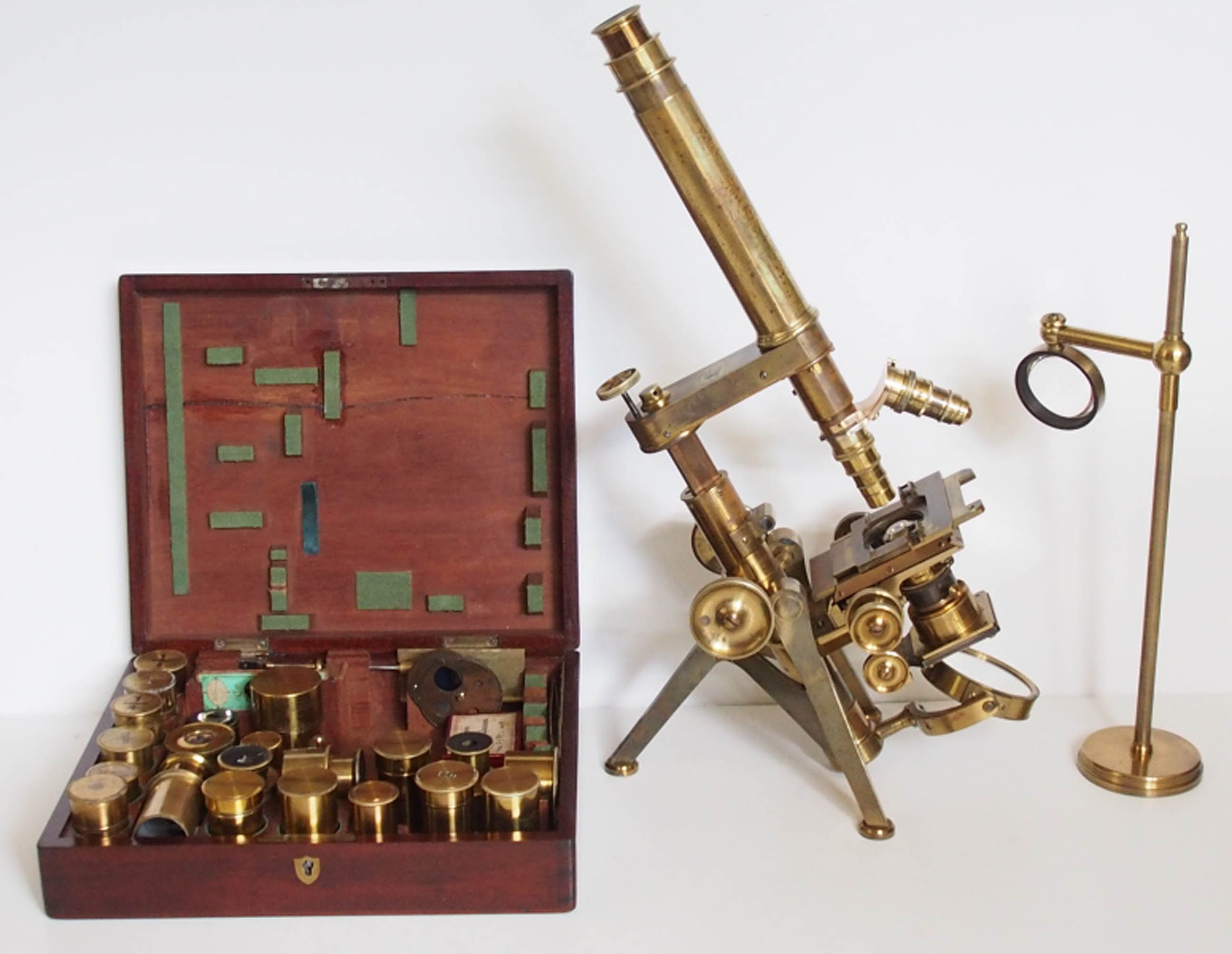
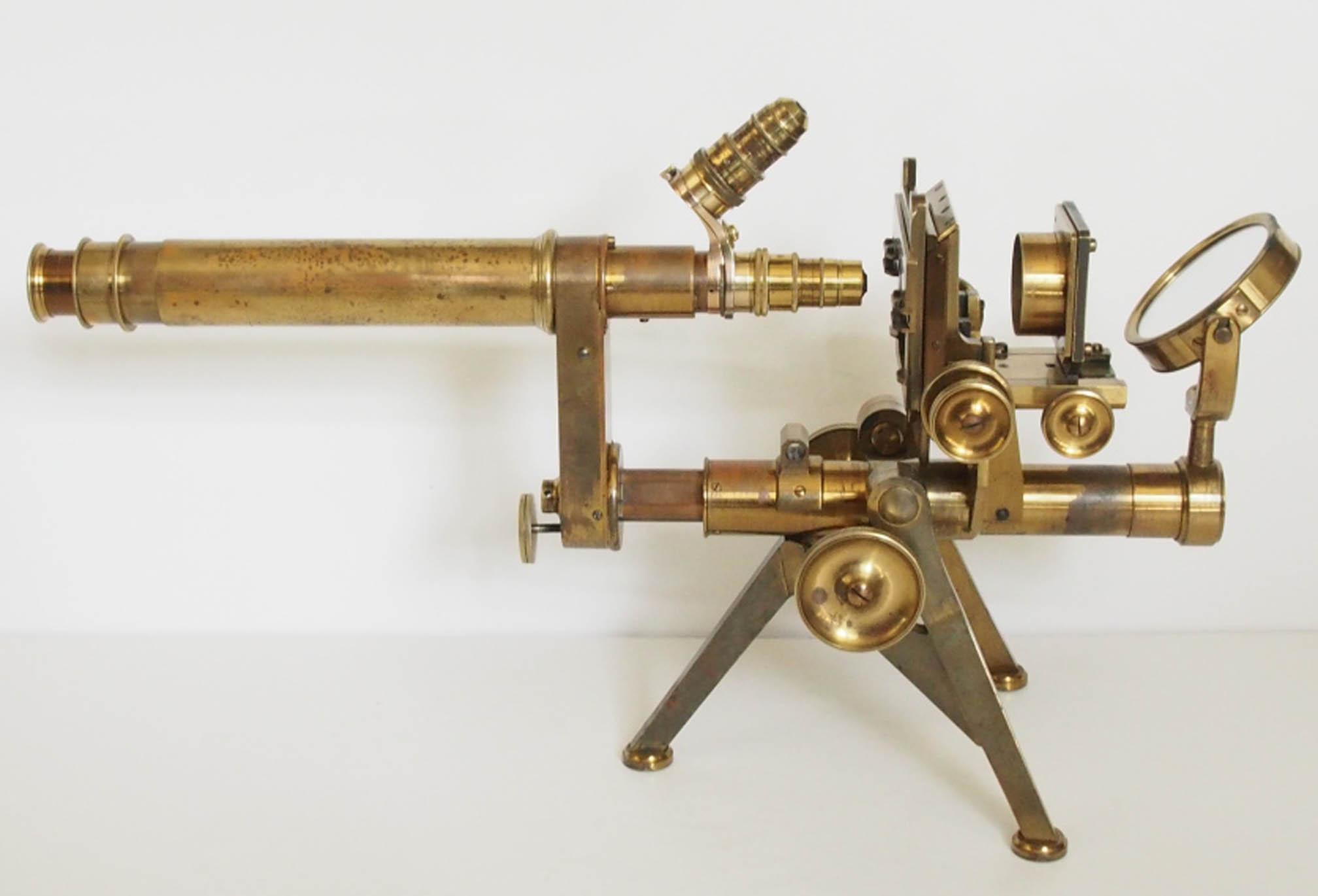
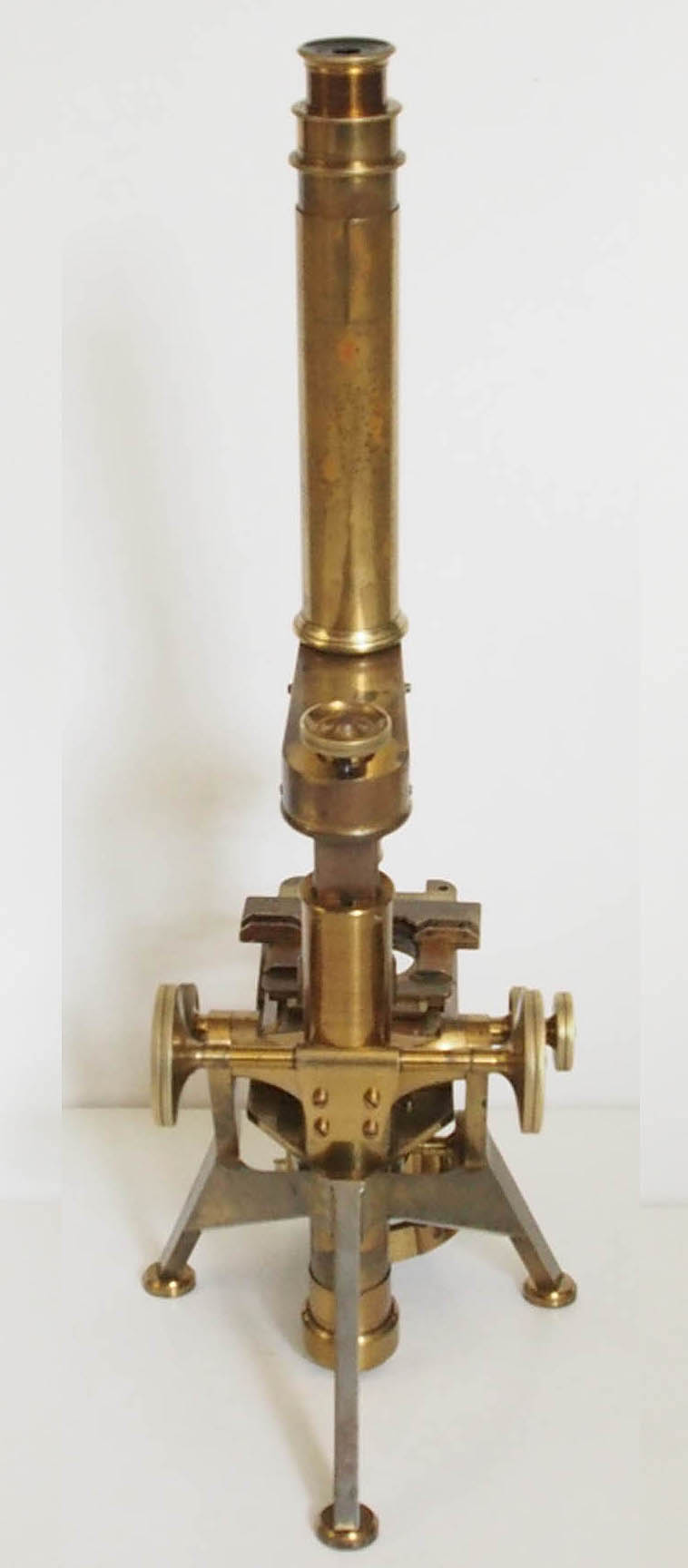
This is an example of Powell & Lealands Compound microscope on an improved construction, referred to in their later catalogues as their No. 3 model. Like its predecessor of 1843, it arises from an English brass tripod foot of 'kettledrum' construction, the span of the front feet measuring 160 mm (6.5 inches), and 170 mm from the front feet to the outside edge of the rear foot (6.7 inches). The front span is the same as the original 1843 model, whereas the front to rear span is about 30 mm shorter. Each foot pad is of round profile, and plugged with cork. The top of the front feet, which are slightly splayed out, is 135 mm (5.25 inches) high, with trunnions at their tops on each side, which allow for a low center of gravity at the body pivot point. The tension of these can be adjusted with a Tommy bar, in the same manner was the 1843 model. The entire tripod including the connecting bands with the single rear leg are cast in one piece. The top and front of the rear leg has curved contours, allowing the microscope to fit into them in the fully vertical and horizontal positions. Unlike the 1843 model, the microscope does not actually touch these parts in these positions but is stopped by internal mechanisms of the inclination joints.
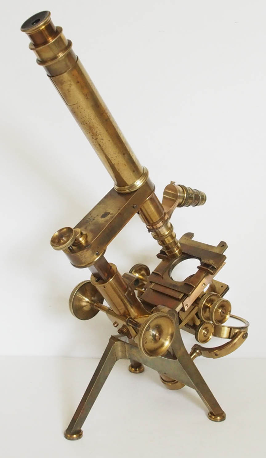
 The bar-limb construction features an arm, which can be rotated aside clockwise through more than 90°, with only one stop aligning the body tube with the optical axis. It can be fixed in position with a screw at the rear of the limb, which can be tightened with a Tommy bar. On the limb, just above the trunnions, is a push-fit receptacle for stage accessories, such as a stage condenser, or side-reflector.
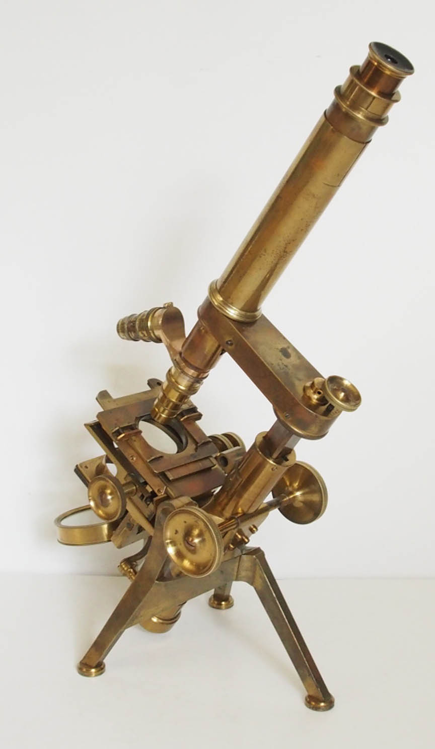
Coarse focus is by a sprung rack-and-pinion acting on the central triangular bar, which is activated by two large knurled knobs, the axis of which is placed only 115 mm above the table surface for ease of operation. Fine adjustment is by means of a screw placed at the very rear of the arm, acting on a long lever concealed within the arm which moves the nose piece, whereby one turn of the screw equates to 0.17 mm of vertical movement. The monocular body tube is screwed directly onto the distal end of the arm, and has a draw tube with an inner diameter of 29.8 mm.
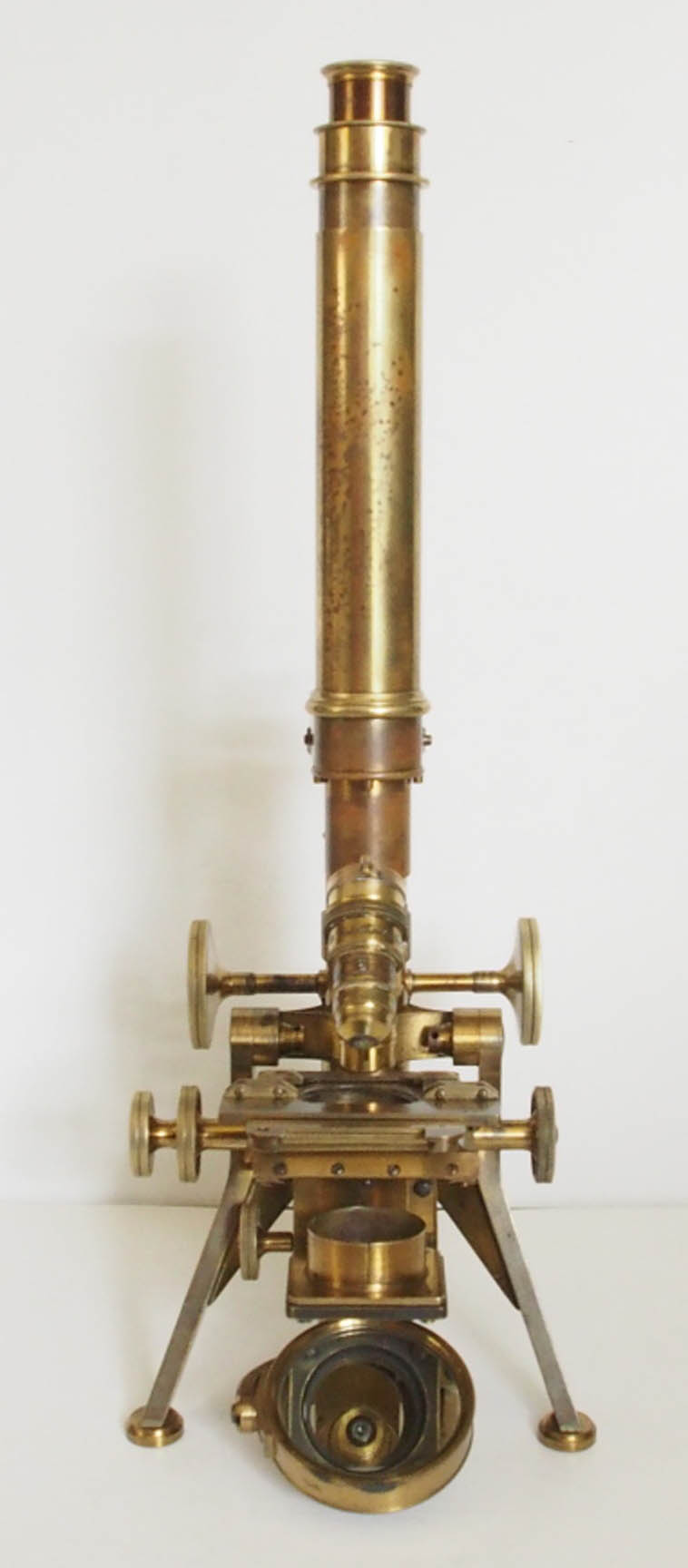
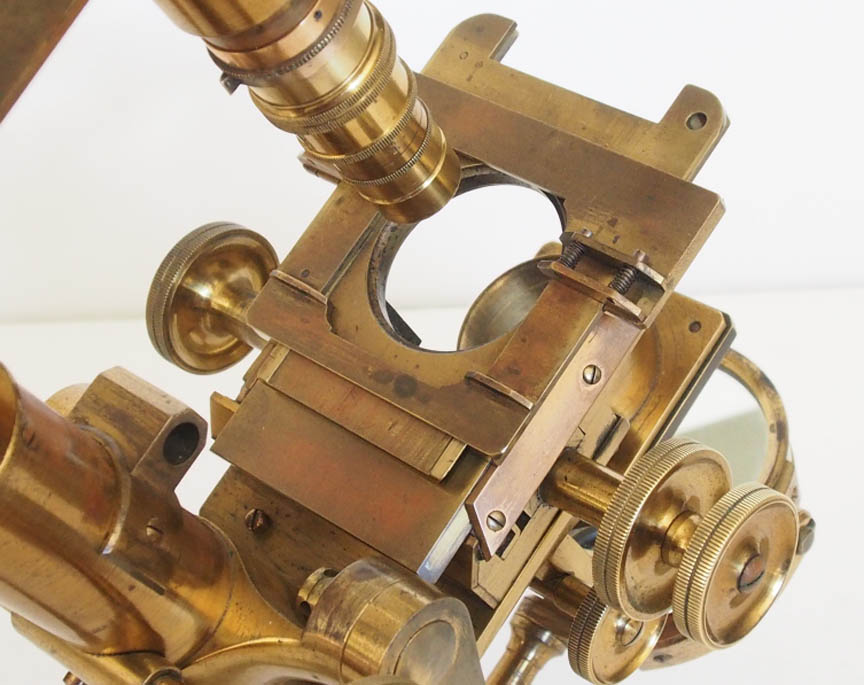 The mechanical stage is of the type invented by Turrell in 1832, with concentric controls. This allows for ¾ of an inch motion in the X- and Y-planes, the X being operated by a cam and follower, and the Y by rack-and-pinion. The entire mechanical stage is attached by four screws to a firm stage plate, which is an extension of the limb. Slides are held in place by one fixed and one sprung sliding bar on the top stage plate, which itself slides on a smaller rectangular plate, which can be rotated 360° by hand. When the top stage plate is pushed back towards the limb, holes on the plate underneath to accept stage mounted accessories like a stage forceps, are revealed. Unlike the early prototype model, there is no longer a sprung safety-stage feature on this later model, which helps reduce the thickness of the stage compared to the 1843 model. Another feature that reduced the stage thickness was the location of the axis of the controls for the stage; this is now under the main stage plate, and the housing for them does not extend all the way forward.
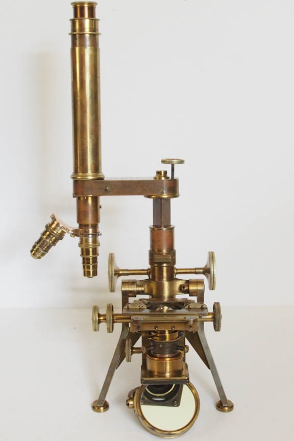
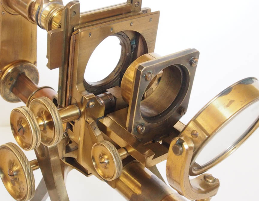 Under the stage is a substage arrangement operated by a single knurled knob on the right-hand side, which acts on a rack-and-pinion. This replaces the plate with a bayonet fitting on the bottom of the stage, as present on earliest models, as well as the slightly later understage slide-in plates to carry substage accessories. On this example, the mechanical eccentric centering movement for the substage, standard on later No. 3 models, is not yet present (see history section). The double-sided mirror has concave and flat surfaces, and, in typical Powell & Lealand fashion, is held by a single curved gimbal, which is attached to a brass sleeve, which pivots and slides on the tail-piece, which is an extension of the lower part of the limb.
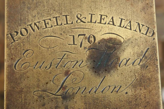
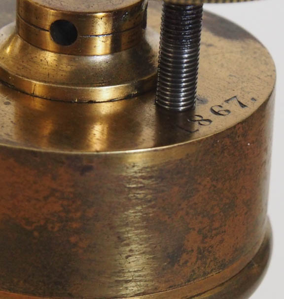
The instrument is signed: Powell & Lealand, 170 Euston Road, London, and is dated 1867.
The original case measures 475 x 230 x 255 mm, and is made of high-quality polished Spanish mahogany. An accessory case, measuring 270 x 230 x 70 mm, slides in vertically, and is held in position by supports covered in green felt. A rectangular piece of mahogany slides into the front bottom of the case, locking the front feet firmly in position with the door closed, preventing movement during transport.
ACCESSORIES:
When purchased, no original accessories were present save for a 10X eye piece. Over the years, the present owner has added a full complement of period accessories, some made by Powell & Lealand, but most by other or unknown makers. This has returned this microscope to a usable instrument again, which can be enjoyed while examining period slides. It is also good to remember that many microscope sets made by Powell & Lealand and other makers belonging to eminent microscopists now in the collection of The Royal Microscopical Society (RMS) carry various accessories not original, and sets were customized by their original owners to suit their individual needs.
Accessories now with this No. 3 microscope include:
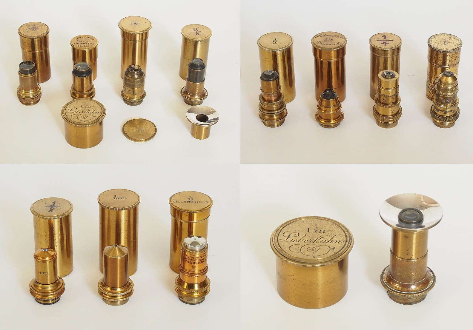
Objectives:
Focal length Angle/N.A. Maker
2 inch 11°/0.09 Unknown
1½ inch 25°/0.21 Unknown
1 inch 23°/0.20 Unknown
2/3 inch 23°/0.20 Smith & Beck (with fitting Lieberkühn)
½ inch 60°/0.51 Unknown ?Swift
4/10 inch 70°/0.57 Hudson & Son, Greenwich
¼ inch 95°/0.73 Powell & Lealand
1/5 inch 100°/0.77 Powell & Lealand
1/8 inch 120°/0.86 Probably by C Collins
1/10 inch 120°/0.86 Probably by C Collins
1/12 inch Oil immersion, N.A. 1.30 J Swift and Son
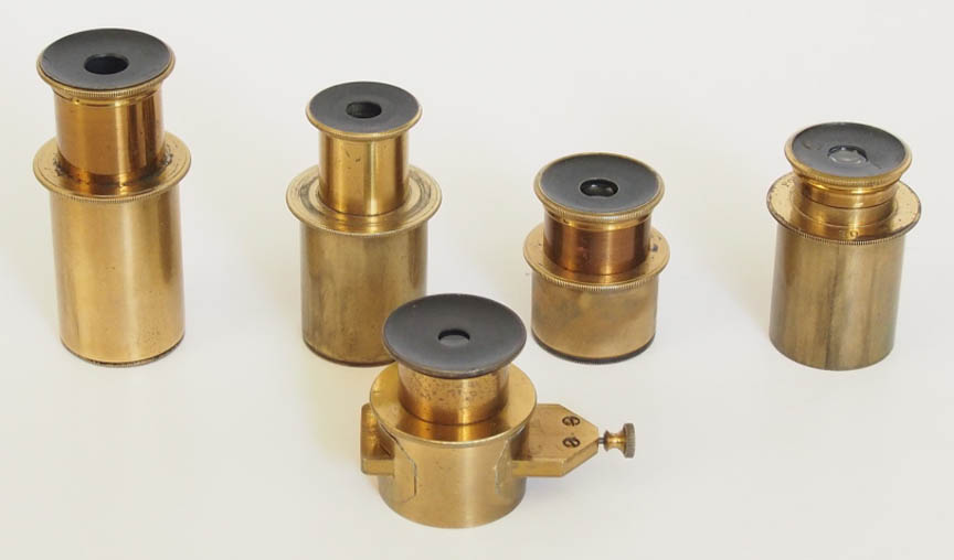
Eyepieces:
Four top hat eye pieces 29.8 mm diameter: x5, x7.5, x10, x20 (P&L)
Jackson-type eye piece micrometer x10, Ramsden design
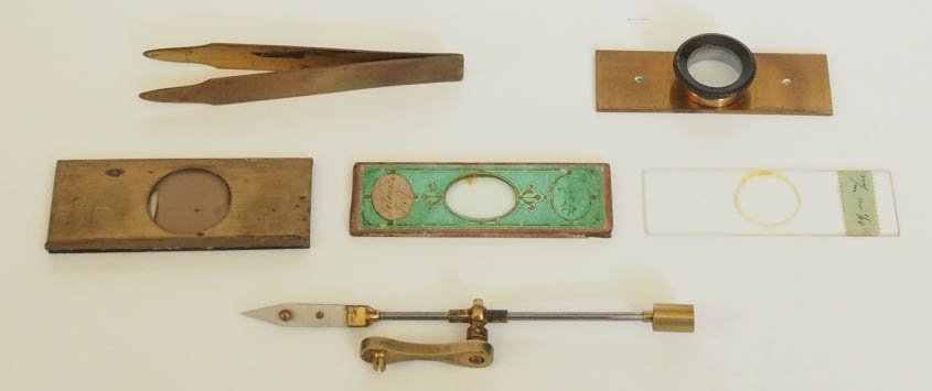
Stage accessories:
Stage forceps
Live box
Stage finder (different from Maltwood) brass-mounted
Stage micrometer in 0.1 and 0.01 mm
Red/Green selenite slide
Brass tweezers
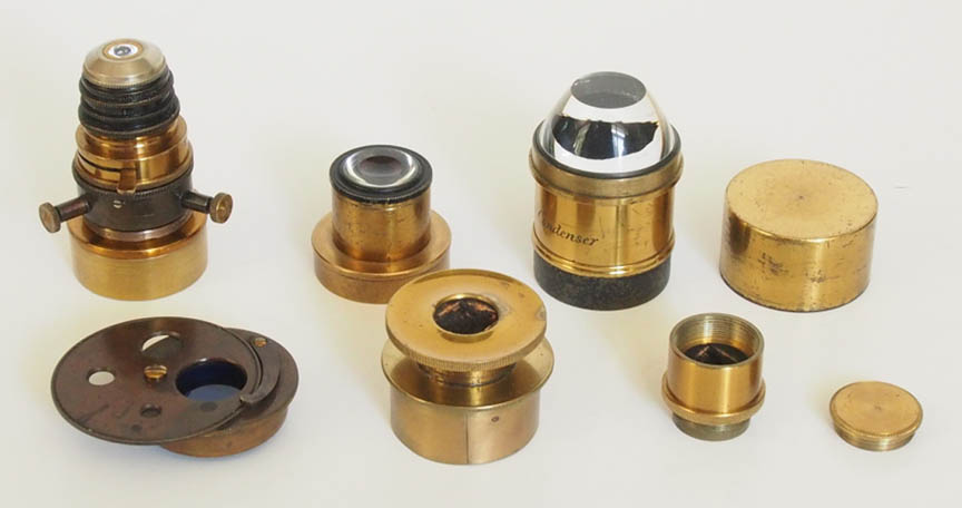
Substage accessories:
Watson holoscopic oil immersion condenser mounted on Davis shutter used as diaphragm, and centering mount for P & L 36.5 sleeve fitting. Full N.A. 1.30 (immersion), 1.0 (dry), 0.60 (top lens removed), 0.32 (both top lenses removed)
Diaphragm with Raineys light modifier (P & L)
Spotted lens for low-power darkground (P & L)
Polariser and analyser by unknown maker, plus extra analyser in can
Dr Edmunds condenser for immersion dark ground and oblique illumination made by P & L in 1877
HISTORY OF THE POWELL & LEALAND No 3 STAND MICROSCOPE:
Prior to the business association with his brother-in-law, Hugh Powell had produced other models of microscope stands, notably the massive model, commissioned by the Royal Microscopical Society, and a Lister-limb model in 1841, both of which featured a Turrell mechanical stage of the type used in his later models.
What is now referred to as the No. 3 model was a direct development of Powell & Lealands New Microscope of 1843. That microscope formed the prototype of the famous group of stands, later to be referred to as Powell & Lealand No.s 1, 2, 3, and 4. The original model was first described in the November 1843 issue of The London Physiological Journal. It was supported on a lighter, but still very stable, version of the tripod than found on their later first-class stands, which featured rectangular legs and supporting feet. The body is carried on trunnions, and has a transverse arm carrying the long lever fine adjustment, which moves the nose-piece. On the earliest examples, like the one on this site the fine focus control, which moves a cone, was placed on the right-hand side of the arm. In 1848, Powell & Lealand had also developed a portable version of this model, with folding feet, and with these the fine focus adjustment control was placed in the familiar vertical position on top of the arm behind the pivot, and from that time on, this position for the fine focus was adopted for all their subsequent microscopes.
For some years, the optical tube was also supported by a set of diagonal stabilizing struts (presumably to reduce vibration) extending from the back of the arm to the upper third of the tube. These were later abandoned, but were still featured on examples dated as late as 1860. Over the 60 years following 1843, this model evolved in different ways. Some examples retained the ranker legs and round feet of the later No. 3 model (see the example dated 1850 in the RMS collection, and one dated 1852 from the Frank collection), whereas others featured the more solid rectangular legs and feet, these forming the prototype of the later No. 1 and No. 2 models, and, mistakenly, these transitional models are often referred to as No. 3 models in sources such as auction catalogues, and even in some books.
As shown on the example on this site, the earlier models featured a thicker stage. That stage was considerably thicker, and there being no substage, accessories such as an achromatic condenser, paraboloid, diaphragm stops, spot lens, or polarizer were affixed to the bottom plate of the stage by means of a bayonet fitting. A special plug-in achromatic condenser was developed for this purpose, with its own rack-focusing mechanism, as well as a knob which remotely controlled the aperture and oblique illumination stops from below, as the stops themselves were located within the body of the stage when the condenser was in focus. With the development of transitional models, such as that of 1856, which featured a separate rack and pinion substage, the disadvantages of this thick stage arrangement were realized, and on subsequent models a thinner stage was adopted. It still took a few years before a separate substage was uniformly adopted. A direct comparison page illustrates changes differences between the 1843 original model, and the 1867 version of the No 3.
In the Billings collection is an early version of the No. 3 stand (silver-plated by a previous owner!) dated 1865, which still carries a separate plate for substage accessories below a by now thinner stage, and it is likely that the final form of this model, featuring a mechanical eccentric centring movement activated by two milled knobs, was not uniformly adopted until after 1869. This also matches the description in Powell & Lealands 1871 catalogue: Substage, with rectangular, and vertical motions for the adoption of the achromatic condenser, paraboloid, &c. It is of interest that this centering arrangement is not present on this 1867 example, even though a focusing substage is present. This may, yet again, represent another transitional form.
With these changes the design of what was by now referred to as the No. 3 stand reaches its mature form. Being as functional as the No. 2 stand, which cost £26-0-0 (without accessories), at a price of £18-10-0 for the No. 3 stand, this resulted in very few of the No. 2 stands being sold, and this explains why today they are relatively rare. By 1899 the No. 3 stand could still be had for £25-0-0, and this continued in Powell & Lealands final 1904 catalogue, after which time only the No. 1 stand was still available, through the firm of Baker as their agent. R.H. Nuttall (in: Powell & Lealand 1900-1925) mentions: I am advised that a No. 3 exists dated 1915, this microscope being equipped with alternative monocular and binocular tubes was at one time in the possession of Mr Peter Sartory. Unfortunately, the present whereabouts of this unique instrument is unknown.
*We are grateful to Dr Jurriaan de Groot for providing the images and text about this instrument on our site for everyone to enjoy.