MICROSCOPE-ANTIQUES.COM © 2013-23.
HAND-MAKING A REPLACEMENT RACK FOR AN ANTIQUE MICROSCOPE
AUTHORS: Barry Sobel and Jurriaan de Groot
Antique microscopes often have damaged racks and occasionally, the rack is even missing. One of us (BJS) had a fine example of a Ross exhibition model bar-limb microscope. For many years Barry was frustrated by not having any way of repairing this instrument which was lacking its rack and had a damaged pinion. But when Jurriaan came to visit, with his extensive self-taught skills, we were able to repair it to work extremely well. This page will describe how, with only hand tools one can make a new rack. If you have a well-equipped machine shop and have access to customized cutters for a rack, you could use a mill for this purpose, but this is not easily obtained. One of us, (BJS) owns a Sherline mill, but making a customized cutter is beyond his skills. This article discusses how we cut the teeth for a working rack (with 83 teeth), using only a hack saw and files, using a shorter but otherwise very similar rack as a guide. It also covers our solution to the damaged pinion. Although the replacement parts are not absolutely identical to the original, the end result works and looks like the original.
Fortunately for us, the rack was not very wide, and the pinion quite wide, so part of the pinion on each side of center was preserved. Also fortunate, was the fact that the rack for the substage has the same teeth as the original main coarse focusing rack, though perhaps a bit thicker overall. This allowed us to use the substage rack as a template and guide-jig for fabricating the new rack.
We first needed to determine how thick the rack should be. This was determined by measuring the distance between the bottom of the rack slot and the edge of the housing where the rack fit into the casing enclosing the bar. We reduced the thickness of the brass piece which was to be the new rack to the correct thickness using my mill.
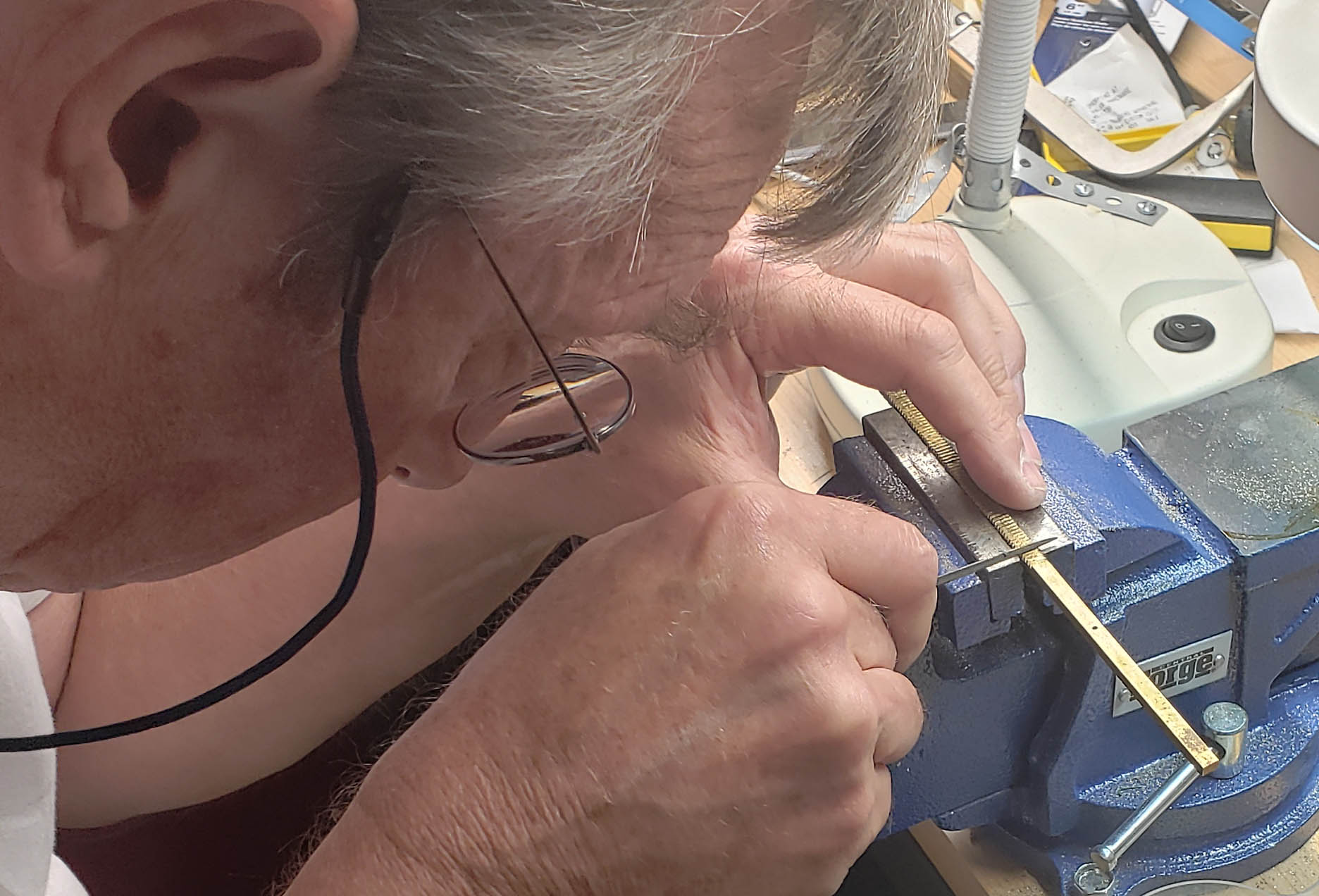
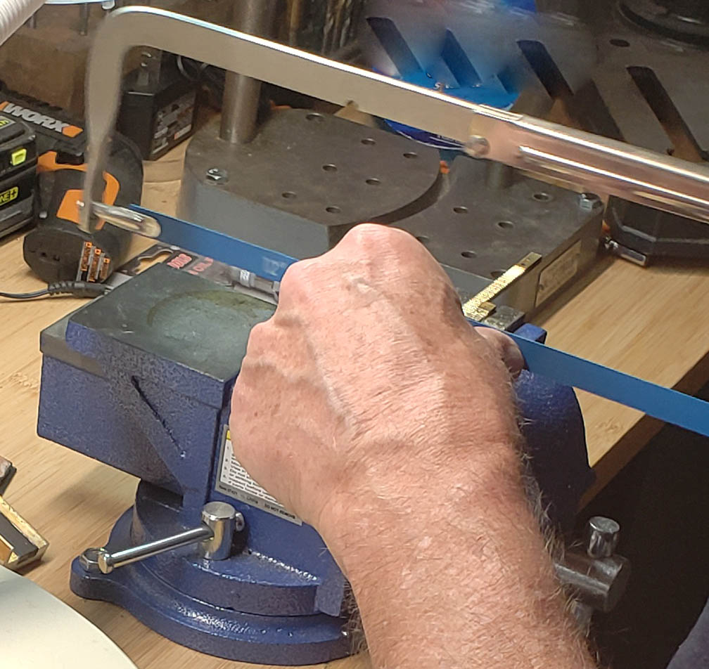 The next step was to remove the substage rack and clamp it in a strong vice next to and parallel to the brass piece that was to become the new rack. A hack saw with a new blade was then used to cut the slots between the teeth. The blade was placed in the grooves of the substage rack at a slight angle until the new rack was scored well, then leveled out horizontally for the cut. The cuts were made to the same depth as the substage rack. Because the substage rack is only about a third as long as the main rack needed to be, once the teeth of the first portion were finished, the substage rack was moved further down using a few of its teeth to line up with the first part of the rack being cut. This was repeated again further down until all 83 teeth were cut. It is important to keep the saw blade vertical and at a right angle from the long edge to the rack during these cuts; the image shows how Jurriaan used his left thumb and index finger (avoiding the teeth of the sawblade), to keep the saw blade both vertical and straight across the rack. This helped to keep the cut vertical and prevent the blade from veering off in a diagonal direction from the right angle required to cut a stright-toothed rack. After the cuts, all the slots were inspected from the side to be sure they were of the correct depth.
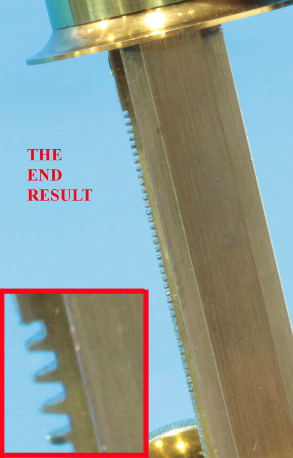
The profiles of the teeth of the rack are not simply squared off. To match the correct profile, a special triangular file was used. Two of the sides are smooth and the third is the cutting side; this allows the smooth sides of the file to register on the prior, and then the following tooth. This process was repeated for all the teeth. The teeth were carefully inspected from the side to make sure they were all shaped properly and any that were not shaped enough were filed further.
The rack also had to be thinner at its distal end so there were no teeth there allowing the rack to engage the pinion and again this reduction in thickness was done on my mill. The screws were all countersunk. Just as the original, the new rack has two countersunk screws at the top of the rack as well as one distally. The distal end of the rack sits on the curved surface of the bar however and a thin piece of brass with a round-filed bottom was added under the rack at the lower end so it sat nicely on the curved tube at the bottom of the bar and the rack was not subject to bending below the bottom of the rectangular bar.
The next issue was the pinion. The damaged center section was removed on my lathe, but this could have been done by hand in a variety of ways. The axle holding the pinion then had to be modified to move towards one side to utilize the remaining preserved portion of the rack while still fitting well into the knobs. The axle had to be shortened on one side and the holes for the pins holding it redrilled, using the holes in the knobs as guides. The axle also needed to be reshaped to fit inside the knobs properly as the axle is not straight but rather conical and the taper therefore needed to be redone to fit the knobs properly. The taper work could be carefully done by hand but I used my Sherline lathe for this.
After the bar was re-installed, the adjustment screws were utilized to allow everything to work just right, with enough tension, but not more than needed. The tension needs to be good enough so the the bar would not simply fall after being raised when all parts (the binocular tube, double nose piece, and two objectives), were attached. The result, delayed for decades, was amazingly good. Smooth action, without any issues was achieved. There was no adverse effect to the cosmetic appearance other than the fact that the slots in soem of the screws holding the pinion box together were difficult to remove and this resulted in some of the slots becomming slightly uneven even with the use of Kroil to loosen them.